4. Loosen but
do
not remove the mounting cap screw
at the front
of
the actuator: then slide the actuator
to the rear enough
to
clear the slotted motmting tab
and the selector shaft.
KC295A
INSTALLING
I. Lubricate the
0-ring
on the actuator;
th.en
ensure
that all mounting surfaces are clean and free
of
debris.
2. Align the actuator with the selector shaft: and slide
it forward onto
th
e shaft taking care to e:ngage
th
e
cap screw in the slot
of
the front mounting tab.
AG925
3. While holding the actuator firmly
forwa1rd
, tighten
th
e front cap screw
to
hold the actuator in place;
then install but do not tighten the two remaining
cap screws.
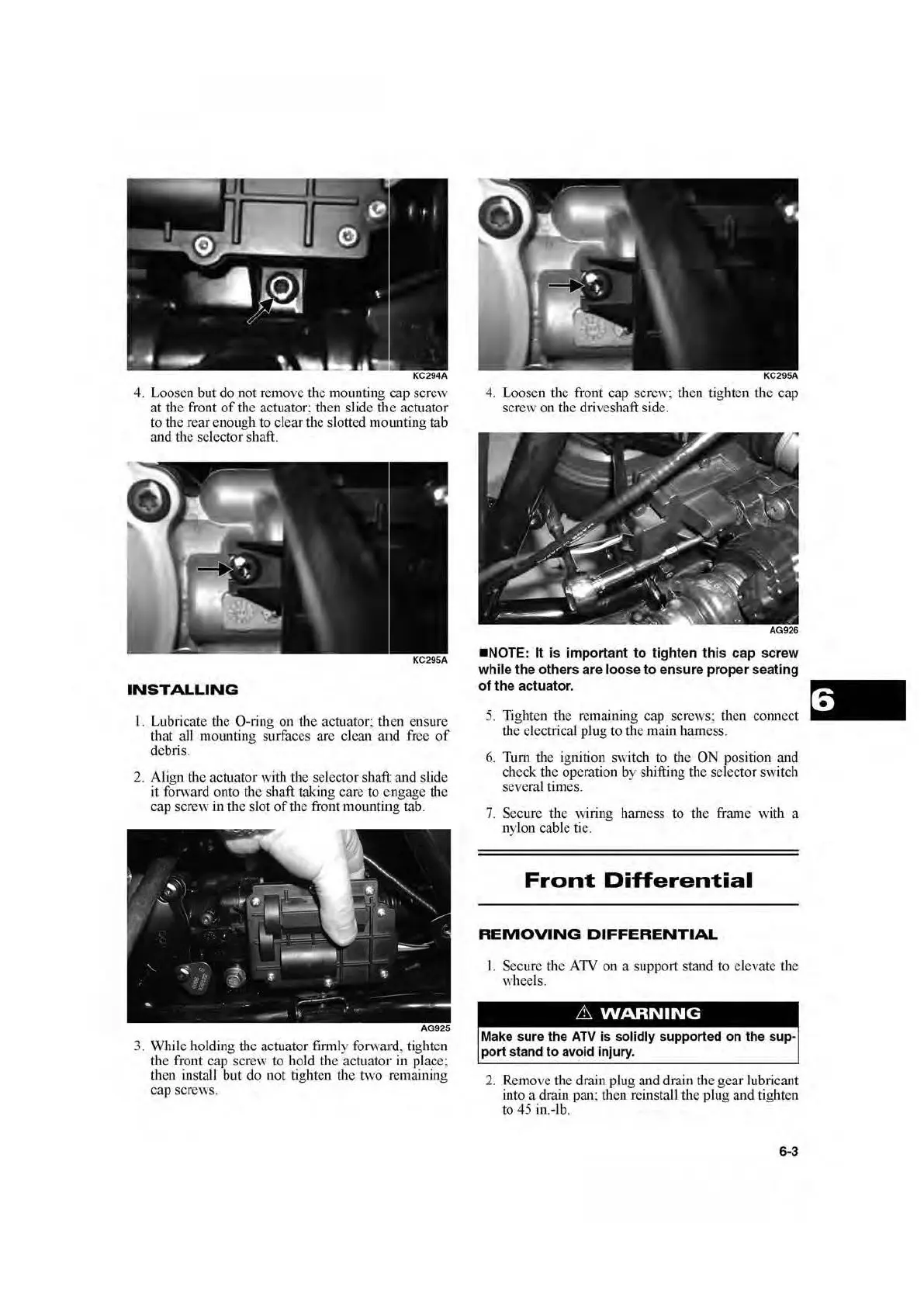
4. Loosen the front cap screw; then tighten the cap
screw on
th
e driveshaft side.
•NOTE
: It is important to tighten this cap s
cr
ew
while the others are loose to ensure
pr
oper seati
ng
of the actuato
r.
5.
Tighten
th
e remaining cap screws: then connect
th
e electrical plug to
th
e main harness.
6.
Turn the ignition switch
to
the ON position and
check the operation
by
shifting the selector switch
seve
ra
l times.
7. Secure the wiring hamess
to
the frame with a
nylon cable tie.
Front
Differential
REMOVING
DIFFERENTIAL
L Secure tbe ATV
on
a support staud
to
elevate the
wheels.
Make s
ur
e the
AT
V is solidly supported on the sup-
port stand to avoid injury.
2. Remove the drain plug and drain the gear lubricant
into a drain pan; then reinstall the plug and tighten
to 45 in.-lb.
6-3
 Loading...