Electrical
System
This section has
been
organized into sub-sections
which show procedures
for
the complete servicing
of
the
KYMCO
ATV electrical system.
• NOTE:
Some
photographs
and
illustrations
used
in
this
section
are used
for
clarity
purposes
only
and
are
not
designed
to
depict
actual
conditions.
General
Instructions
The
ignition
control
module
or
ECU
maybe
damaged
if
dropped
or
the
connector
is
disconnected
when
the
key
is
ON,
the
excessive
voltage
may damage
the
ignition
control
module
or
ECU.
Always
turn
off
the
ignition
switch
before
servicing.
A
faulty
ignition
system
is
often related
to
poor
connections.
Check
those
connections
before
proceeding.
Some
electrical
components
may
be damaged
if
terminals
or
connectors
are
connected
or
disconnected
while
the
ignition
switch
is
ON
and
current
is
present.
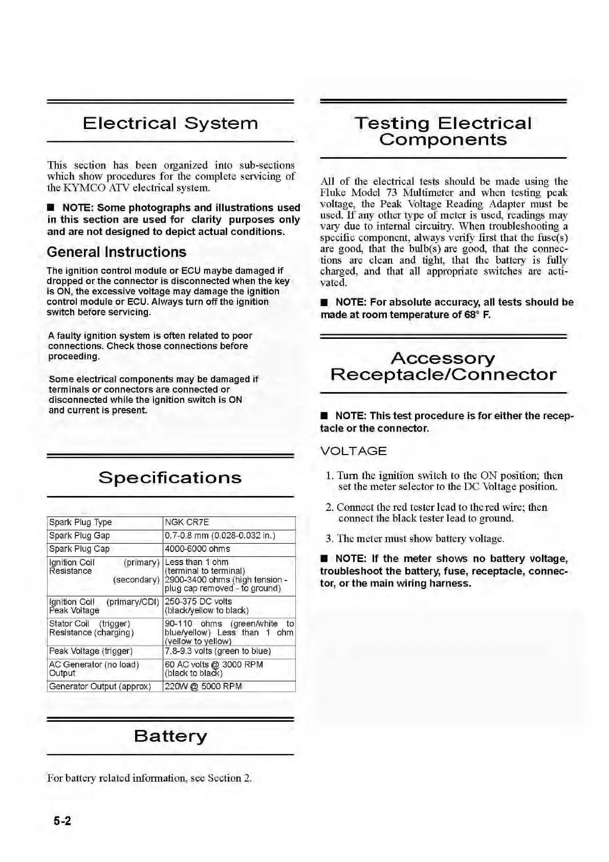
Specifications
Spark
Plug
Type
NGK
CR7E
Spark
Plug
Gap
0.7-0.8
mm
(0.028-0.032
in.
)
Spark
Plug
Cap 4000-6000 ohms
Ignition
Coil
(primary)
Less than 1
ohm
Res
istan
ce
(terminal
to
t
erm
inal
)
(secondary)
2900-3400 ohms (hi
gh
tension-
plug
cap
removed-
to
ground)
Ignition Coil (primary/COl)
250-375
DC
volts
Peak
Vo
lt
age
(black/ye
ll
ow
to
black)
Stator
Coi
l (trigger) 90-110 ohms
(greenAnlhite
to
Resistance (ch
arg
ing) blue/yellow) Less
than
I (yellow
to
yellow)
1
ohm
Peak
Vo
lt
age
(trigger) 7.
8-9.3
vo
lts (green
to
blue)
AC
Generator
(no
load
)
Output
60
AC
vo
lt
s@
3000
RPM
(black to black)
Generat
or
Output (approx) 220W@ 5000
RPM
Battery
For
battery related information, see Section 2.
5-2
Testing
Electrical
Components
All
of
the electrical tests shou
ld
be
made using the
Fluke Model 73 Multimeter and w
hen
testing
peak
voltage, the
Peak
Voltage
Reading
Adapter must
be
used.
If
any other
type
of
meter
is used, readings
may
vary due
to
internal circuitry.
When
troubleshooting a
specific component, always
verifY first
that
the fuse(s)
are good, that the bulb(s) are good, that the c
onn
ec-
tions are cle
an
and tight,
that
the battery
is
fully
charged,
and
that all appropriate switches are acti-
vated
.
• NOTE:
For
absolute
accuracy, all
tests
should
be
made
at
room
temperature
of
68°
F.
Accessory
Receptacle/Connector
• NOTE:
This
test
procedure
is
for
either
the
recep-
tacle
or
the
connector.
VOLTAGE
1.
Tum
the ignition switch
to
the
ON
position;
then
set
the
meter
selector to the
DC
Voltage position.
2. Connect the
red
tester l
ead
to the
red
wire;
then
connect the black tester l
ead
to ground.
3. The meter must show battery
vo
lta
ge
.
• NOTE:
If
the
meter
shows
no
battery
voltage,
troubleshoot
the
battery
, fuse, receptacle,
connec-
tor,
or
the
main
wiring
harness.
 Loading...