CHECKING
AND
CLEANING
DRAIN
1.
Inspect the drain on the
fi
lt
er
housing cover and
clean out any
dirt or debris.
2. Replace
any drain that is. crac.ked or shm•
vs
any
signs
of
hardening
or
detenoratJon.
3. Wipe any accumulation
of
oil or gas from the filter
housing
and
drain.
Valve/Tappet
Clearance
(Feeler
Gauge
Procedure)
To check and adjust
va
lve/tappet clearance, use the
following procedure.
•NOTE:
The seat, left-side and
right
-si
de
engine
covers, and gas
tank
must
be removed
for
this
pro-
cedure.
1.
Remove the timing inspection plug and spark
plug: then
remO\
~
e
the tappet . covers (for J??re
deta.iled infom1atton, see
SectJOn
3 - Serv1cmg
T
op
-Side Components).
2.
Rotate
th
e crankshaft to the TDC position on the
com
pr
ession stroke.
•NOTE:
At
this
point
,
the
rocker
arms
and adjuster
screws
must
not
have
pre
ssure
on
them.
2-6
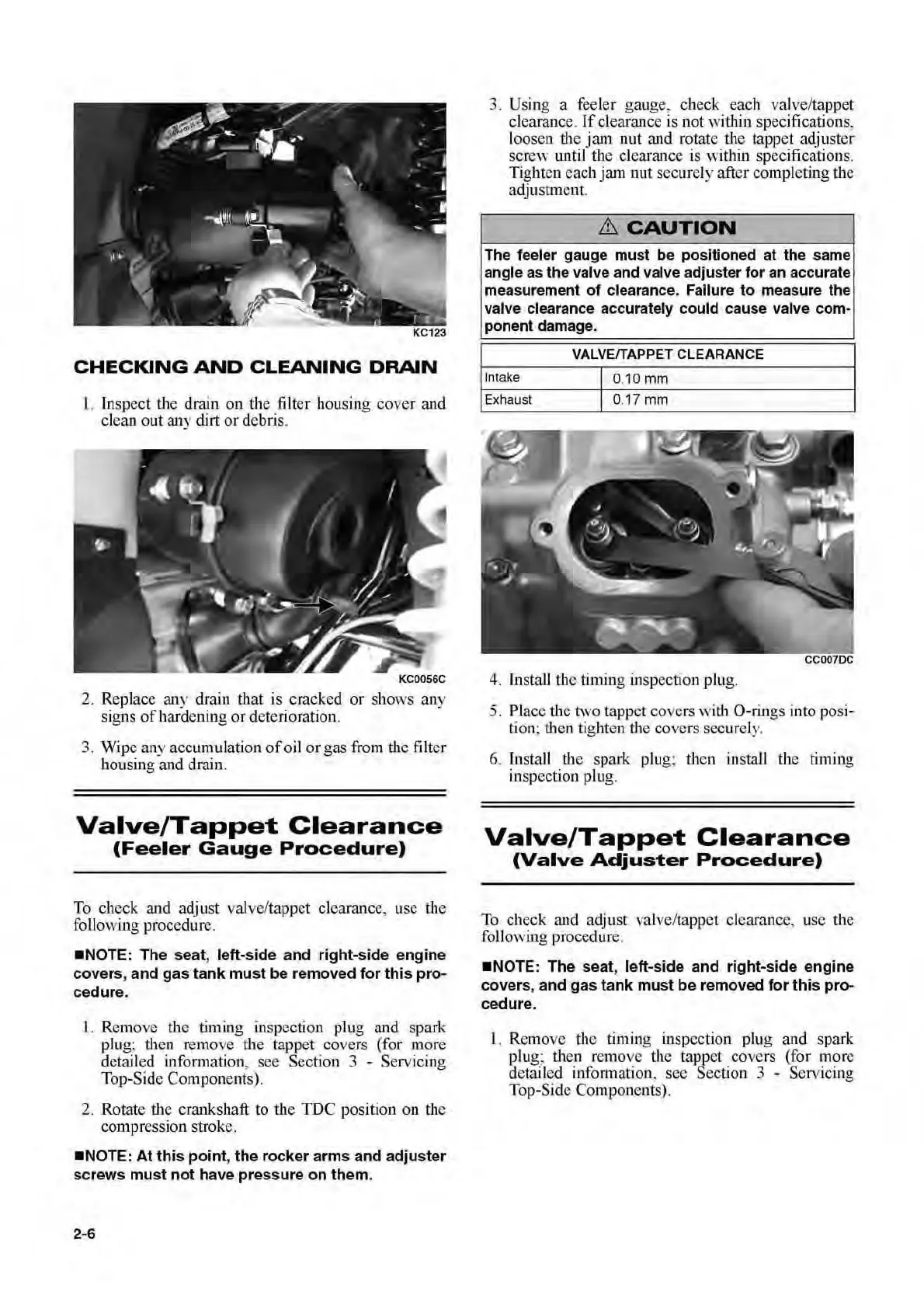
3. Using a feeler gauge, check.
e~c
h
v
a!
ve/
t~pp
et
cl
ea
rance.
If
clearance is not w
1thm
spec
rfi
ca~tons,
loosen the jam nut and
r
~tate
.t
h ~
tapp
e.t
adj~1ster
screw lmtil the cl
ea
rance IS w
1thm
spec
rfi
c~tJons.
Tighten each jam nut secur
ely
after completJng the
adjustment.
&
CAUTION
The feeler gauge must be positioned at the same
angle as the valve and valve adjuster for an accurate
measurement
of
clearance. Failure
to
measure the
valve clearance accurately could cause valve com-
ponent damage.
VALVE/TAPPET
CLEARANCE
Intake
J 0.10
mm
Exhaust
J 0.17
mm
4.
Install the tinting inspection plug.
5.
Place the two tappet covers with
0-rin
gs
into
po
si-
tion: then tighten the covers securely.
6. Install
th
e spark plug: then install the timing
in
spection plug.
Valve/Tappet
Clearance
(Valve
Adjuster
Procedure)
To check and adjust val
ve
/tapp
et
clearance, use the
foliO\\ri.ng
procedure.
•NOTE
: The seat, left-side and right-side engine
covers
, and gas
tank
must
be
removed
for
this
pro-
cedure.
l.
Remove the tim
in
g
in
spec
t.ion
plug and spark
plug: then remove the tappet. covers (for
~?re
detailed information. see S
ectiO
n 3 - Serv
1cm
g
Top-Side Components).

 Loading...