Drive
System
• NOTE:
Some
photographs
and
illustrations
used
in
this
section
are
used
for
clarity
purposes
only
and
are
not
designed
to
depict
actual
conditions.
• NOTE:
Critical
torque
specifications
are
located
in
Section
1.
• NOTE:
Specifications
regarding
the
gear
cases
(capacities,
ll.bricant
type,
etc.)
can
be
found
in
Section
1
of
this
manual.
Ring Gear Backlash 0.28-0.38 mm (0.011-0.015 in.)
Ring Gear End
Play 0.1-0.2
mm
(0.004-0.008 in.)
GENERAL
INFORMATION
All
gear
cases are tagged beneath a cover bolt. This tag
is marked with a production date code, sequence code,
and
a ratio code.
The
"1"
or "3.1" on the lower-right
comer
indicates a
3.1:1
gearsetratio
(11:34teeth).
The die-cast aluminum housings have been assembled
with thread-rolling screws (trilobular). When
assem-
bling with these screws, start the screws carefully into
the housing; then use the
following torque values.
New Reassembled
Size
Housing Housing
M6 (Torx
T-30
Recess) 8-9.5 fl-lb 6.5-9 fl-lb
M8 (Torx
T-40
Recess) 25-31 fl-lb 21-25 fl-lb
M1
0 (Torx
T-50
Recess) 37-45.5 fl-lb 31-38 fl-lb
6-2
SPECIAL
TOOLS
A number
of
special tools
must
be available to the
technician
when
performing service procedures in this
section.
Description p/n
CV Boot Clamp Tool
Internal
Hex Socket
Pinion Gear/Shaft
Removal
Tool
Slide Hammer Kit
Gear
Case Seal Installer
Tool
E014
• NOTE:
Special
tools
are available
from
the
KYMCO
Spare
Parts
Department.
Front
Drive
Actuator
• NOTE:
The
actuator
is
not
a
serviceable
compo-
nent.
If
it
is
defective,
it
must
be
replaced.
• NOTE: The
actuator
wi
II
operate
only
when
the
ignition
switch
is
in
the
ON
position.
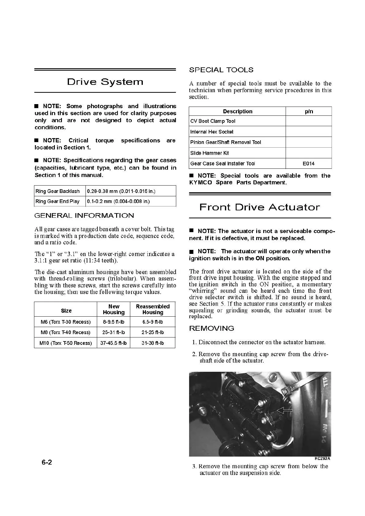
The front drive actuator is located on the side
of
the
front drive input housing.
With
the engine stopped and
the ignition switch in the
ON
position, a momentary
"whirring" sound can be heard each time the front
drive selector switch is shifted.
If
no sound is heard,
see Section 5.
Ifthe
actuator runs constantly or makes
squealing
or
grinding sounds, the actuator
must
be
replaced.
REMOVING
1. Disconnect the connec
tor
on the actuator harness.
2. Remove the mounting cap screw from the
drive-
shaft side
of
the actuator.
3. Remove the mounting cap screw from below the
actuator on the suspension side.
 Loading...