RESISTANCE
.&.
CAUTION
II
Always disconnect
the
battery when purforming
resistance tests
to
avoid damaging
the
mul·llmeter.
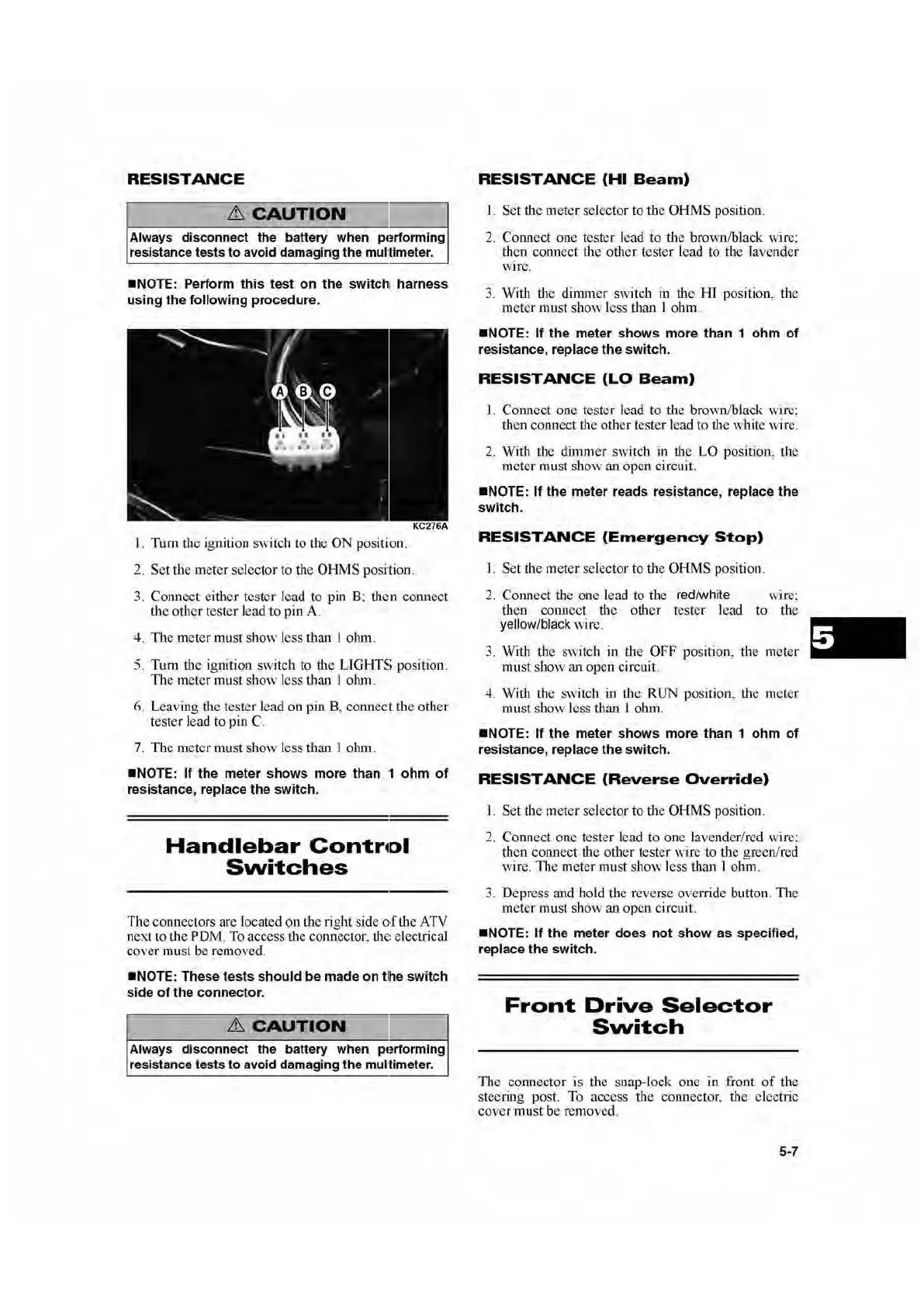
•NOTE:
Perform
this
test
on
the
switch
t
harn
ess
using
the
following
procedure
.
1. Turn the ignition S
\,
·
itc
h to the ON position.
2.
Set
the meter select
or
to the OHMS position.
3. Connect
either
tester l
ea
d to pin B; the n connect
Ote
othe
r tester l
ead
to
pin A.
4.
Th
e m
eter
must
show
J
ess
than I ohm.
5. Tum the ignition switch to
the
LI
GHTS
position.
The meter must
show
l
ess
than l olun.
6. Leaving
the tester
lead
ou
pin
8, connect the
other
tester lead to pin
C.
7.
Tb
e meter
must
show
l
ess
than 1 ohm.
•NO
TE:
If
the
meter
shows
more
than
1
ohm
of
resistance
, replace
the
switch.
Handlebar
Contr•ol
Svvitches
The
co1
m
ec
tors are located
Qn
t
he
right
si
de
a.f lbe
ATV
n
ext
to the P DM. To access the connector.
th
e:
electrical
coYer must
t>e
re
mov
ed.
•NOTE
:
Th
ese
tests
sh
ould
be
made
on
tlhe
switch
side
of
the
connector
.
&
CAUTION
ll
Always disconnect the battery when pt!rforming
resistance tests to avoid damaging
the
mul'limeter.
RESISTANCE
(HI
Beam)
1. Set the meter selector to
the
OH
MS
position .
2. Connect
one
tester l
ea
d to
tJ1e
brown/black wire:
then
connect the
other
t
ester
l
ead
to
the
lavender
WJre.
3.
With
the
dinuner
switch i.n the
HI
position,
th
e
meter must
show
less than I ohm.
•N
OTE:
If
t
he
meter
shows
more
than
1
ohm
of
resistance, r
eplace
the
switc
h.
RESISTANCE
(LO
Beam)
1. Connect
one
tester l
ead
to
tJ1e
brown
/black wire:
th
en
connect dte other tester lead to the white w
ir
e:
2.
Wi
th
the
dimmer
switch in the LO position, the
rueter must
show
an
open
circuit.
•N
OTE:
If
the
meter
reads r
es
i
stance
, r
eplace
the
switch.
RESISTANCE
(Emergency
Stop)
1. Set
the
meter selector to the
OHM
S position.
2.
Connect the one l
ead
to the red/white wire;
then com1cct the
other
tester lead
to
the
yellow/black wire.
3. Wi
th
the
sw
itch
in
the OFF position, the
meter
mu
st
show
an open circuit.
4.
With the switch
in
the RUN position, the meter
mu
st
show
loss than I ohm.
•N
O
TE
:
If
the
meter
shows
more
than
1 o
hm
of
res
istance
, replace
the
swi
t
ch
.
RESISTANCE
(Reverse
Override)
I.
Set
the meter sel
ector
to the
OH
MS position.
2.
Connect
one
tester lead to
one
lavender/red wire:
then connect
the
other
tester wire
to
the green/red
w
ir
e.
T11
e meter must sh
ow
less than I ohm.
3. Depress and hold
the
reverse override button.
Th
e
meter must
show
an
open
circuit.
•N
OTE:
If
the
meter
does
not
show
as
specified
,
replace
the
switc
h.
Front
Drive
Selector
Svvitch
The connector is the snap-lock one
in
front
of
the
steering post. To access tbe
colutector, tbe electric
cover
must be remo
ved
.
5-7

 Loading...