•NOTE
: When testing t
he
HI fuse holder, the head-
light dimmer switch mu
st
be
in
the
HI position;
when testing
the
LIGHTS fuse holder,
the
headlight
dimmer switch
ca
n
be
in e
ith
er
po
sition.
•N
OTE:
If
the
meter shows no battery
vo
ltage,
troub
les
hoot
the battery,
switc
hes,
distribution
module,
or
the
main
wiring
harness.
Fuses
~
CAUTION
II
Always disconnect
th
e battery when porformlng
resistance tests
to
avoid damaging the mul·timeter.
I Set the meter
se
lector to
t11e
OHM
S position.
2. Connect the red tester lead to ono spade end
of
the
fuse; then connect the black tester lead
to
the other
sp:ldc end.
3.
Th
e meter mu
st
show less th
an
I obm resistan
ce
.
If the
me
t
er
reads open.
re
pl
ace the tltsc.
•N
OTE
: Make
su
re the fuses are return
ed
to
their
prop
er
position according
to
amperage. Refer
to
the fuse
bl
ock
cover
for fuse placement.
Ignition
Coil
The ignition
co
il is on the frame above the engine. To
access
the co
il
, t
he
left side
panel
mu
st be rc
11t10
ved.
RESISTANCE
~
CAUTION
II
Always disconnect the battery when
pt~rforming
resistance tests
to
avoid damaging the muHimeter.
•N
OTE
: For
th
ese tests,
th
e meter selecltJr
shou
ld
be
set
to
the
OHMS
position
and the! primary
wire(s) s
hould
be
disconnected.
Pr
ima
ry
Winding
I. Connect the red tester lead
to
ei
ther t
enninal:
then
connect the
bl
ad,
tester lead to the other temtinal.
2. The meter reading must
be
''
ithin specification.
Secondary
Winding
I. Remove the plug cap from the high tensio11 l
ea
d.
then conn
ec
t the red t
es
t
er
l
ea
d to the
l1i
gh tension
l
ea
d.
2.
Connect the black tester lead to ground.
3. l11e met
er
reading must
be"
ithin speci
fi
cation.
•N
O
TE
: If the meter does
not
show
as
specified,
replace
ig
nition
coil.
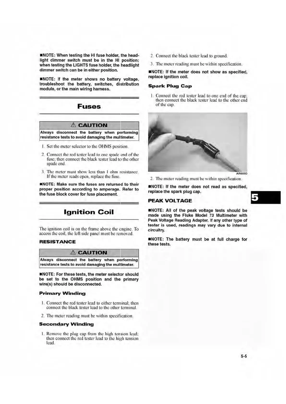
Spark
Plug
Cap
I. Connect
tl
1e red tester lead to one e
nd
of
t
he
ca
p:
th
en connect
tJ1
e black tester lead to t
he
other end
of
U1
e
ca
p,
2. l11c meter reading must be within speci
fi
ca
tion.
•N
OTE:
If
the meter does
not
read
as
specified,
replace the spark
plug cap.
PEAK
VOLTAGE
•N
OTE: All
of
th
e peak
vo
ltage
te
sts
should be
made using the Fluke Model
73
Multimeter
with
Peak Voltage Reading Adapter. If any other
type
of
tester is used, readings may vary due
to
internal
circuitry.
•N
OTE: The battery mu
st
be
at
full char
ge
for
these tests.
5-5

 Loading...