Regulator/Rectifier
1l1e
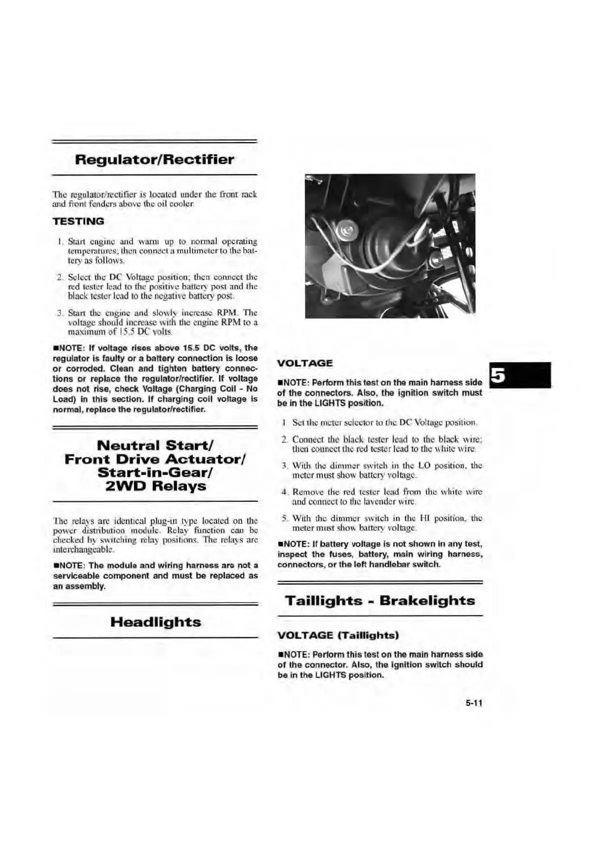
regu
lator/rect:iuer
is
located under
the
front
rock
an
d
front
fe
nd
ers above
th
e
oi
l cool
er
.
TESTING
I. Start engine
a1
1d
wa
nn
up
to
n.ormal operating
le
mp
l:ralures;
IJ
1on co
nn
ect a multunetcr to
th
e bat-
tery
as
follows.
2. Select the
DC
Voltage
position;
th
en connect
d1c
red
te
ster lead to
the
positive battery post and
U1c
black
te
ster lead
to
the
nogati,,o battery post.
3. Start
the
en
gi
ne
and sl
o"
I)
increase
RPM
.
1l1c
, oltage should increase with
the
engine
RPM
to
a
maximtun
of
I ·
.5
DC
volts.
•NOTE:
If
voltage rises above
15
.5
DC
volts, the
regulator Is faulty
or
a battery connection
is
loose
or
corroded. Clean and tighten battery connec-
tions
or
replace the regulator/rectifier.
If
vo
lt
age
does
not
rise, check Voltage
(C
harging Coil - No
Load)
in
this
section.
If
charging
coil
voltage
is
normal, replace the regulator/rectifier.
Neutral
Start/
Front
Drive
Actuator/
Start-in-Gear/
2WD
Relays
Thtl
relavs
are identical plug-in type located on
tb
e
power
rl"is
rribut
ion
module.
Re
lay function can be
cht:cked
b)'
S
\\
itching rel:l) positions. Th
e:
rel<l)
s arc
interchangeable.
•N
OTE
: The module and wiring harness a
re
not a
serviceable component and must
be
replaced as
an assembly.
Headlights
VOLTAGE
•N
O
TE
: Perform this test
on
the m
ai
n harness side
of
the co
nn
ectors. Also, the ignition switch must
be in the LIGHTS
po
si
tion.
I
Set
the
meter selector
to th
e DC Voltage position
2.
Couuect
tbc
bbck
tes
ter
lead
to
th
e black
wi.re:
tbeo
CO
ilJl
cct the
red
tester lead
to
the wbitc wire.
3. With the dimmer swi
tch
in
the LO position. tbc
meter must show battery voltage.
4_ Remove the
red
tester lend
from
the
white wi
re
a
nd
connect
to
tllc la
ve
nd
er
wiro
.
5. With the din1mer switcb
in
th~;
HI position. the
meter must sho\\ battery
vo
ltage.
•N
O
TE
:
If
battery voltage
is
not
shown in any
test
,
inspect the fuses, ba
tt
ery
, main wiring harness.
connectors,
or
the
left handlebar
sw
itch.
Taillights
-
Brakelights
VOLTAGE
(Taillights)
•N
O
TE
: Perform
this
test
on
the main harness s
id
e
of
the connector. Also, the igniti
on
switc
h
sho
uld
be in the
LI
GHTS
po
sition.
5-11

 Loading...