About X-431 Station
DiagnosticsToolbox & AppsFAQ
Initial Use
109
www.x431.com +86 755 8455 7891
LAUNCH
Station
User's Guide
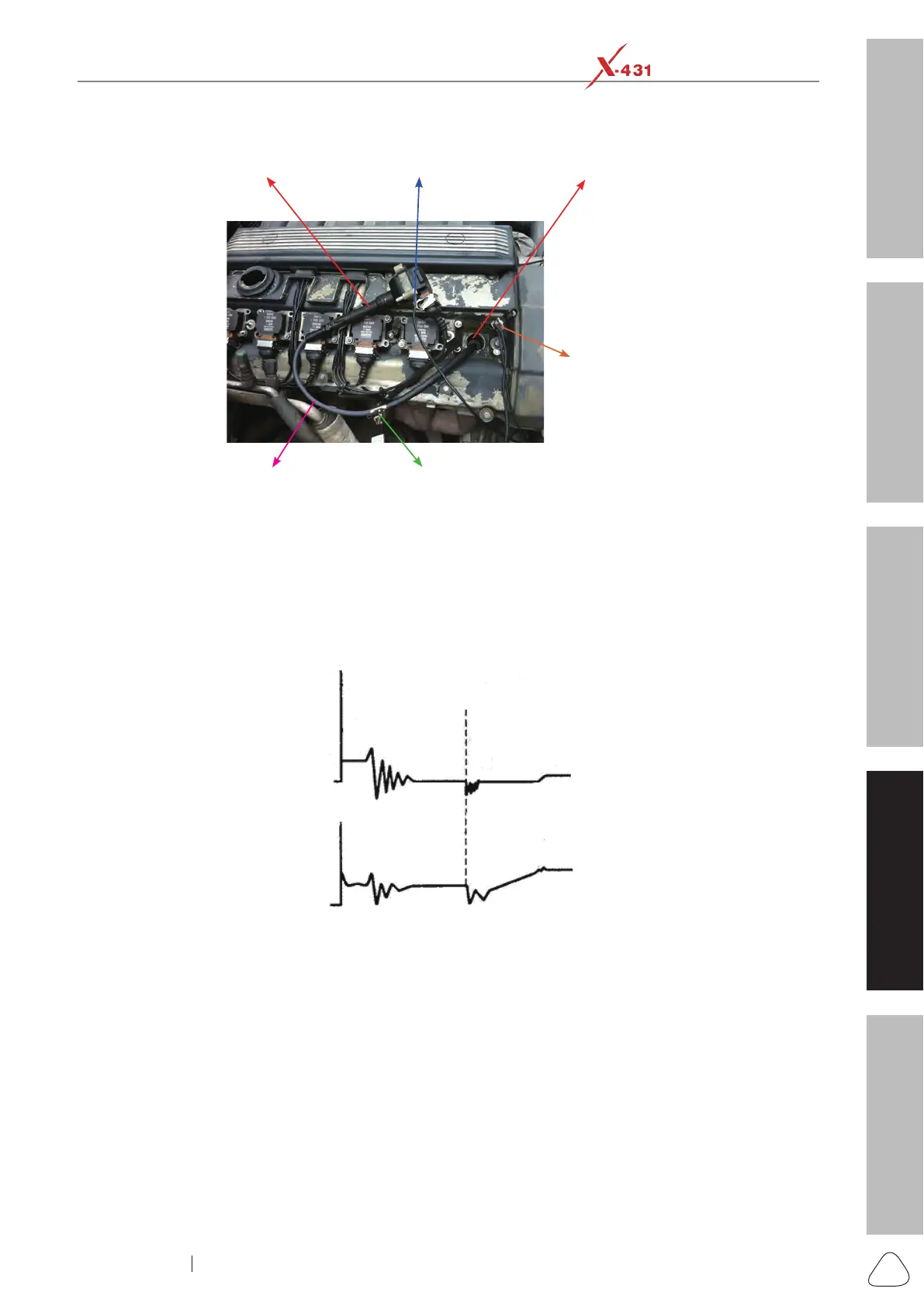
The connection is as follows:
COP earth
cord &
crocodile clips
to ground
Ignition coil
COP earth cord
COP extension
cord
The high-voltage clips to
the insulated lead of the
COP extension cord
Spark plug
Connection Method
Fig. Ignition-3 shows the normal secondary (the upper one) and (the lower one) primary ignition waveform
of direct ignition system. Beause the on/off of primary circuit is not opening/closing of mechanical contact,
but the conduction of transistor. The primary voltage has no obvious oscillations within the duration, but
the voltage increases during the magnetization process due to current limiting, and this change can cause
corresponding uctuations of secondary voltage line as a result of induction of ignition coil.
Fig. Ignition-3
4.4.4 Waveform analysis mode
The ignition secondary single-cylinder waveform test is mainly used to:
a. Analyze the ignition dwell angle of single cylinder.(ignition coil charging time)
b. Analyze the capability of ignition coil and secondary high tension circuit (from ignition line to ignition
voltage line).
c. Find the improper mixture A/F ratio of single cylinder (from combustion line).
d. Analyze the capability of capacitance (platinum or ignition system).
e. Find the spark plug that causes misre of the cylinder (from combustion line).
This test can provide very meaningful information about the combustion quality for each cylinder. If
necessary, this test can also be performed during driving. Since the secondary ignition waveform is
signicantly affected by different engines, fuel systems and ignition conditions, it is useful for detecting the
faults of engine mechanical parts, fuel system components, and ignition system components. Different
parts of the waveform can specify that some components and systems on the specic cylinder have faults.

 Loading...