About X-431 Station
DiagnosticsToolbox & AppsFAQ
Initial Use
81
www.x431.com +86 755 8455 7891
LAUNCH
Station
User's Guide
5 Battery clamps cable
To supply power to the Sensorbox through connection to
vehicle's battery.
6 Electronic control converting cord 1
7 Electronic control converting cord 2
4.1.3 Sensor Simulation
1). Connections
1. Connect the B-shaped terminal of data cable to the B-shaped port of the Sensorbox, and the other end to
the Data I/O port of the USB hub.
2. Plug one end of the sensor test cable (black) into the “COM” interface of the Sensorbox, then connect the
other end to the test probe or electronic control converting cable.
3. Connect one end of the sensor test cable (red) into the “VΩHz” interface of the Sensorbox, and then
connect the other end to the test probe or electronic control converting cable.
Note: Choose corresponding cables and test probes according to different terminals.
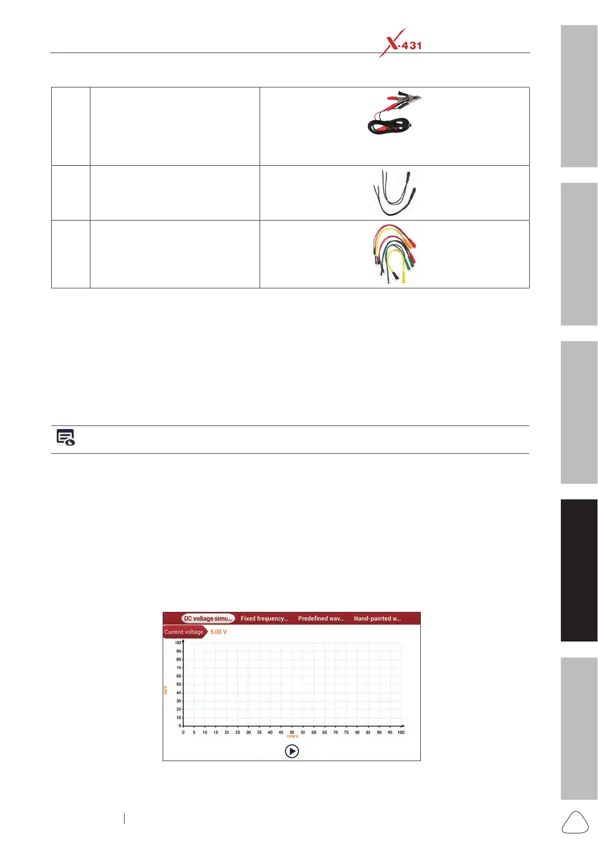
2). Simulation test
Simulation test enables users to exactly judge if the sensor is good or not to avoid replacing components
blindly. For example, the trouble code indicates the fault is in water temperature sensor itself. But we need
to conrm whether the fault results from water temperature sensor or the connections between ECU and
sensors, or ECU itself. In this case, we can make full use of simulation test to input the signal of simulating
water temperature sensor, instead of water temperature sensor, to the microcomputer. If the engine works
better and the fault vanishes, the fault is in the water temperature sensor. If the fault still occurs, input the
signal to the corresponding terminals of ECU. Consequently, if the fault disappears, the fault lies in the
connection between water temperature sensor and ECU, otherwise, the fault exists in ECU.
After all connections are properly made, launch the X-431 Station application. Go to “Toolbox”, then tap or
click “Sensor Simulation” to enter the test selection screen.
Fig. Sensor-1

 Loading...