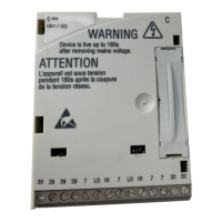
System bus (CAN / CAN−AUX) configuration
Setting the CAN node address and baud rate
8
155
EDBCSXA064 EN 3.2
8 System bus (CAN / CAN−AUX) configuration
The codes for the system bus (CAN / CAN−AUX) configuration can be found in the GDC
parameter menu under System bus. They are divided into separate code ranges:
Interface Code range
X4 System bus (CAN) C03xx
X14 System bus (CAN−AUX) C24xx
Tip!
More detailed information on the CAN bus can be found in the appendix of
this documentation ( 440).
8.1 Setting the CAN node address and baud rate
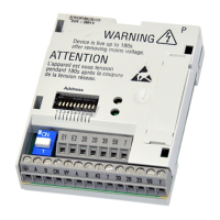
For the CAN interfaces X4 (CAN) and X14(CAN−AUX), the CAN node address and the
transfer rate can be set via the DIP switch S1 or via codes.
ƒ The (address) switch 1 serves to define whether the set CAN node address shall only
apply to the interface X4(CAN) or for both interfaces X4 (CAN) and X14 (CAN−AUX).
ƒ If one of the (address) switches 2 ... 7 of the DIP switch is switched on (ON), and the
low−voltage supply is connected, the setting of the DIP switch is evaluated and
written into C0350/C2450 (CAN node address) and C0351/C2451 (baud rate).
ƒ If the (address) switches 2 ... 7 are switched off (OFF), the switch position is not
evaluated. The settings from C0350/C2450 (CAN node address) and C0351/C2451
(baud rate) are accepted.
ƒ The settings for the baud rate with the switches 8 ... 10are only written into C0351
(CAN) when the low−voltage supply is switched on. The baud rate for CAN−AUX can
only be set via C2451.
 Loading...
