System modules
MCTRL_MotorControl (node number 131)
Monitoring
13
369
EDBCSXA064 EN 3.2
13.20.14 Monitoring
3
3~
DSP
Digital Signal Processor
mController
CAN
3
PLC program
(acc. to IEC 61131-3, alterable)
Technology functions
Operating system
Drive control
Communication
Motor control
Memory
(FLASH, EEPROM, RAM)
Interfaces
System bus (CAN)
Fieldbuses
Digital frequency
Analog/digital I/O
Rectifier
Inverter
Standard motor
Synchronous motor
Asynchronous motor
with resolver/encoder
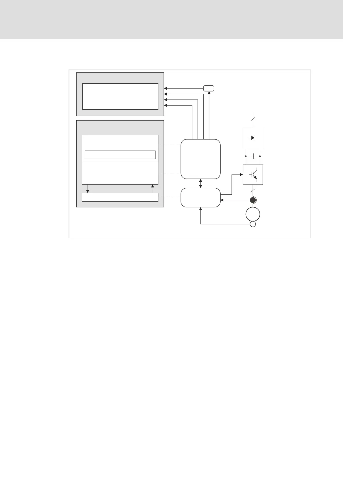
ECSXA292
Fig. 13−32 Signal flow: motor control ˘ PLC
The motor control is provided with different monitoring functions, protecting the drive
against impermissible operating conditions.
If a monitoring function is activated,
ƒ the corresponding response for device protection is initiated.
ƒ the fault indication is entered on the first position in the history buffer ( 237).
ƒ a corresponding variable is set to TRUE as long as the trigger condition is fulfilled.
The variables of the monitoring function can be processed in the application program
of the PLC.
The current error number is also displayed in the variable DCTRL_wFaultNumber after the
PLC has been started.
In the fault history buffer (C0168/x), fault messages are saved in codes as 4−digit numbers.
The first digit describes the type of fault response. The last three digits correspond to the
fault number.

 Loading...


