System modules
CAN3_IO (node number 33)
Outputs_CAN3
13
298
EDBCSXA064 EN 3.2
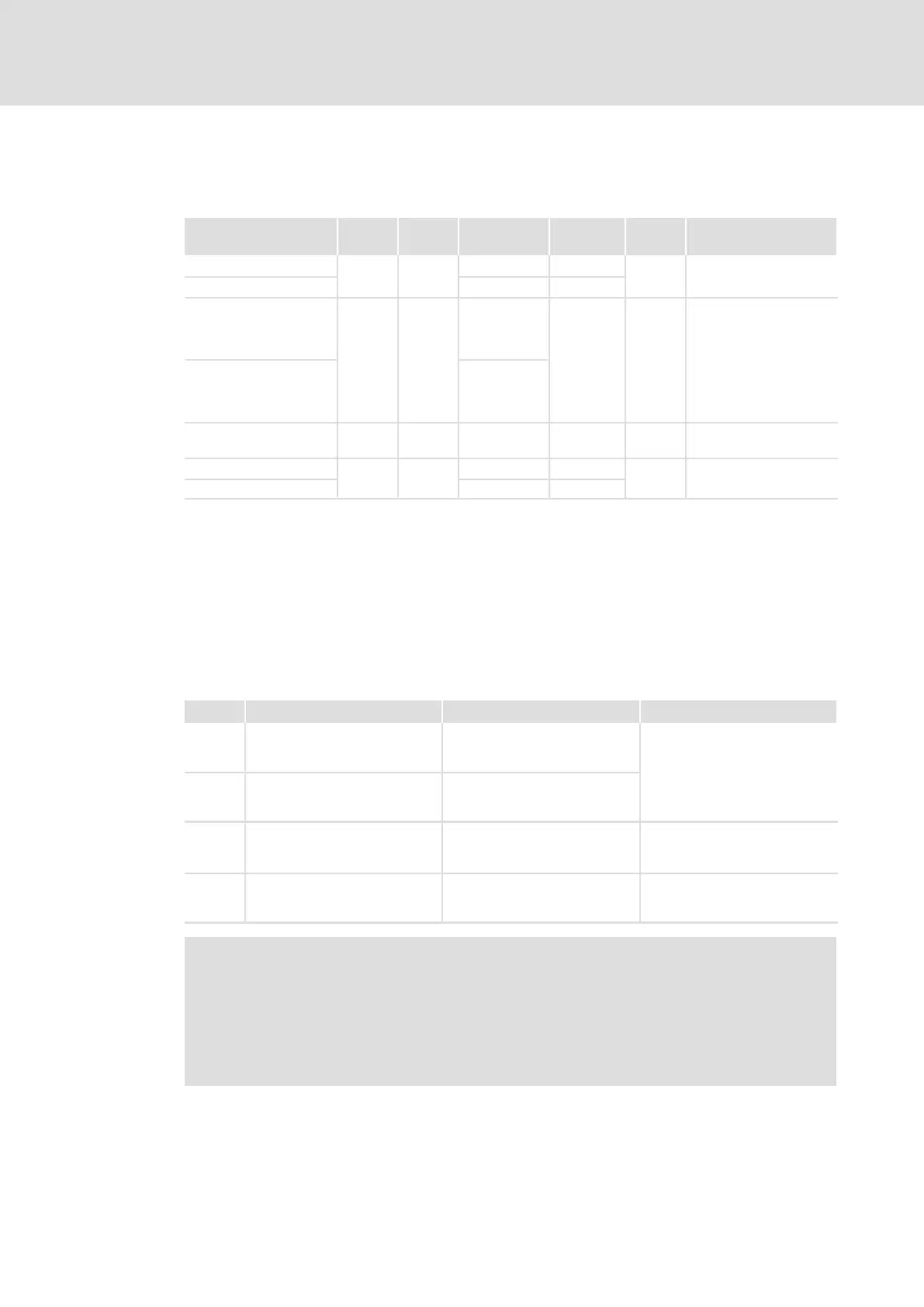
13.10.2 Outputs_CAN3
System variables
Variable Data
type
Signal
type
Address Display
code
Display
format
Comments
CAN3_nOutW1_a
integer
analog
%QW33.0 C0868/8
dec [%]
CAN3_nOutW2_a %QW33.1 C0868/9
CAN3_bFDO0_b
BOOL binary
%QX33.0.0
C0151/3 hex
Display code in hex
as double word
... ...
CAN3_bFDO15_b %QX33.0.15
CAN3_bFDO16_b %QX33.1.0
... ...
CAN3_bFDO31_b %QX33.1.15
CAN3_dnOutD1_p double
integer
position %QD33.0 C0869/3 dec [inc]
CAN3_nOutW3_a
integer analog
%QW33.2 C0868/10
dec [%]
CAN3_nOutW4_a %QW33.3 C0868/11
User data
The first 4 bytes of the 8 bytes user data to be sent can be written via several variables of
different data types. According to requirements, data can therefore be transferred from
the PLC program as
ƒ binary information (1 bit)
ƒ status word/quasi−analog value (16 bit)
ƒ angle information (32 bit)
Byte Variable (1 bit) Variable (16 bit) Variable (32 bit)
1, 2 CAN3_bFDO0_b
...
CAN3_bFDO15_b
CAN3_nOutW1_a
CAN3_dnOutD1_p
3, 4 CAN3_bFDO16_b
...
CAN3_bFDO31_b
CAN3_nOutW2_a
5, 6
CAN3_nOutW3_a
7, 8
CAN3_nOutW4_a
Note!
Avoid simultaneous overwriting via different varianle types to ensure data
consistency.
If you want to describe e.g. the bytes 1 and 2, either use only the variable
CAN3_dnOutD1_p, only the variable CAN3_nOutW1_a or only the variables
CAN3_bFDO0_b ... CAN3_bFDO15_b!

 Loading...


