4-32 Service Manual
5025-2xx, 4xx
Fuser assembly removal
See “Fuser assembly” on page 7-5 for the part number.
1. Remove the right cover assembly. See “Right cover assembly removal” on page 4-12.
2. Remove the left cover. See “Left cover assembly removal” on page 4-6.
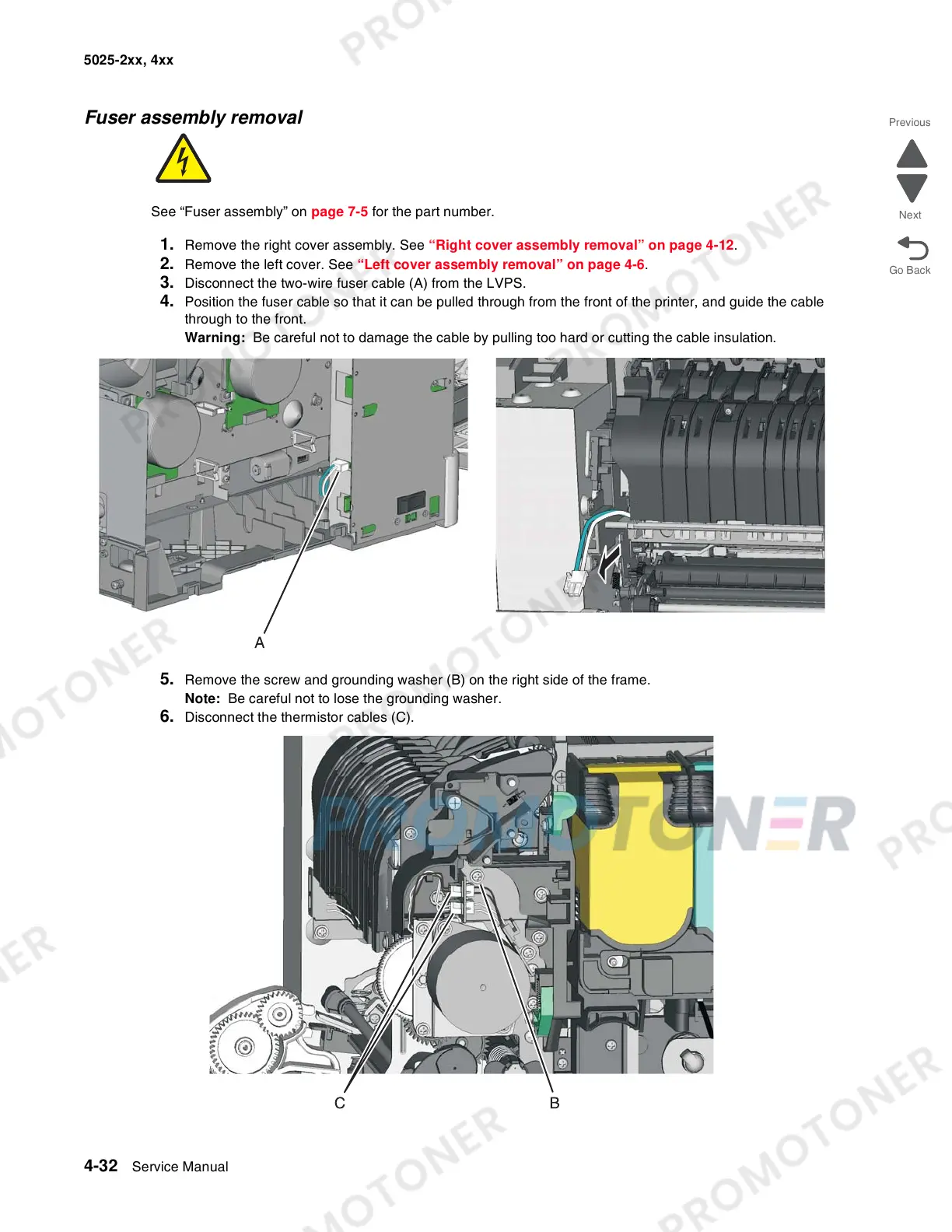
3. Disconnect the two-wire fuser cable (A) from the LVPS.
4. Position the fuser cable so that it can be pulled through from the front of the printer, and guide the cable
through to the front.
Warning: Be careful not to damage the cable by pulling too hard or cutting the cable insulation.
5. Remove the screw and grounding washer (B) on the right side of the frame.
Note: Be careful not to lose the grounding washer.
6. Disconnect the thermistor cables (C).
 Loading...