Diagnostic information 2-33
5025-2xx, 4xx
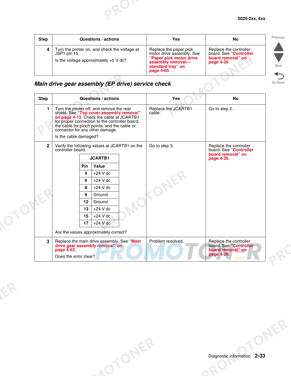
Main drive gear assembly (EP drive) service check
4
Turn the printer on, and check the voltage at
JSP1 pin 15.
Is the voltage approximately +5 V dc?
Replace the paper pick
motor drive assembly. See
“Paper pick motor drive
assembly removal—
standard tray” on
page 4-65.
Replace the controller
board. See “Controller
board removal” on
page 4-20.
Step Questions / actions Yes No
1 Turn the printer off, and remove the rear
shield. See “Top cover assembly removal”
on page 4-13. Check the cable at JCARTB1
for proper connection to the controller board,
the cable for pinch points, and the cable or
connector for any other damage.
Is the cable damaged?
Replace the JCARTB1
cable.
Go to step 2.
2
Verify the following values at JCARTB1 on the
controller board.
Are the values approximately correct?
Go to step 3. Replace the controller
board. See “Controller
board removal” on
page 4-20.
3
Replace the main drive assembly. See “Main
drive gear assembly removal” on
page 4-63.
Does the error clear?
Problem resolved. Replace the controller
board. See “Controller
board removal” on
page 4-20.
Step Questions / actions Yes No
JCARTB1
Pin Value
4 +24 V dc
6 +24 V dc
8 +24 V dc
9 Ground
12 Ground
13 +24 V dc
15 +24 V dc
17 +24 V dc
 Loading...