Diagnostic information 2-29
5025-2xx, 4xx
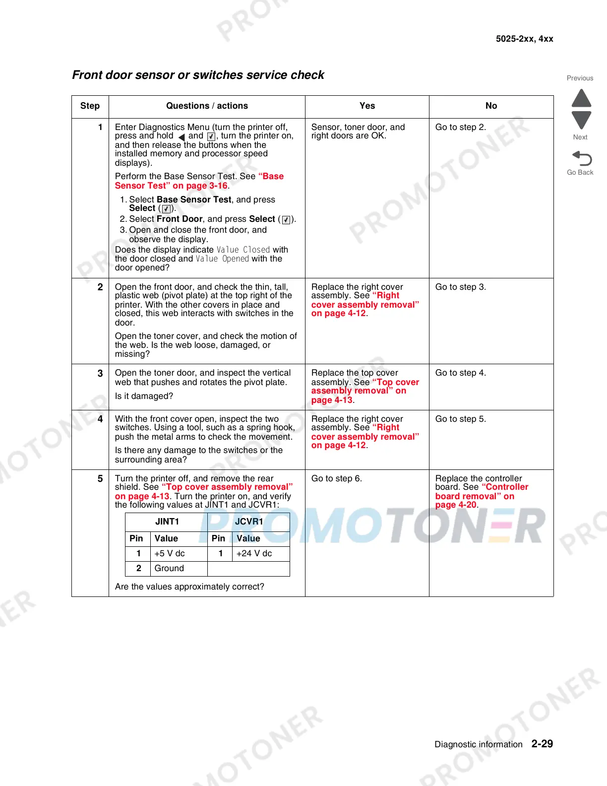
Front door sensor or switches service check
Step Questions / actions Yes No
1 Enter Diagnostics Menu (turn the printer off,
press and hold and , turn the printer on,
and then release the buttons when the
installed memory and processor speed
displays).
Perform the Base Sensor Test. See “Base
Sensor Test” on page 3-16.
1. Select Base Sensor Test, and press
Select ().
2. Select Front Door, and press Select ().
3. Open and close the front door, and
observe the display.
Does the display indicate Value Closed with
the door closed and Value Opened with the
door opened?
Sensor, toner door, and
right doors are OK.
Go to step 2.
2
Open the front door, and check the thin, tall,
plastic web (pivot plate) at the top right of the
printer. With the other covers in place and
closed, this web interacts with switches in the
door.
Open the toner cover, and check the motion of
the web. Is the web loose, damaged, or
missing?
Replace the right cover
assembly. See “Right
cover assembly removal”
on page 4-12.
Go to step 3.
3
Open the toner door, and inspect the vertical
web that pushes and rotates the pivot plate.
Is it damaged?
Replace the top cover
assembly. See “Top cover
assembly removal” on
page 4-13.
Go to step 4.
4
With the front cover open, inspect the two
switches. Using a tool, such as a spring hook,
push the metal arms to check the movement.
Is there any damage to the switches or the
surrounding area?
Replace the right cover
assembly. See “Right
cover assembly removal”
on page 4-12.
Go to step 5.
5
Turn the printer off, and remove the rear
shield. See “Top cover assembly removal”
on page 4-13. Turn the printer on, and verify
the following values at JINT1 and JCVR1:
Are the values approximately correct?
Go to step 6. Replace the controller
board. See “Controller
board removal” on
page 4-20.
JINT1 JCVR1
Pin Value Pin Value
1 +5 V dc 1 +24 V dc
2 Ground
 Loading...