Driving modes
6.5 Installing/removing the outrigger beams
6 - 34 3 302 690 en Operating manual
GMK4100L-1
23.11.2017
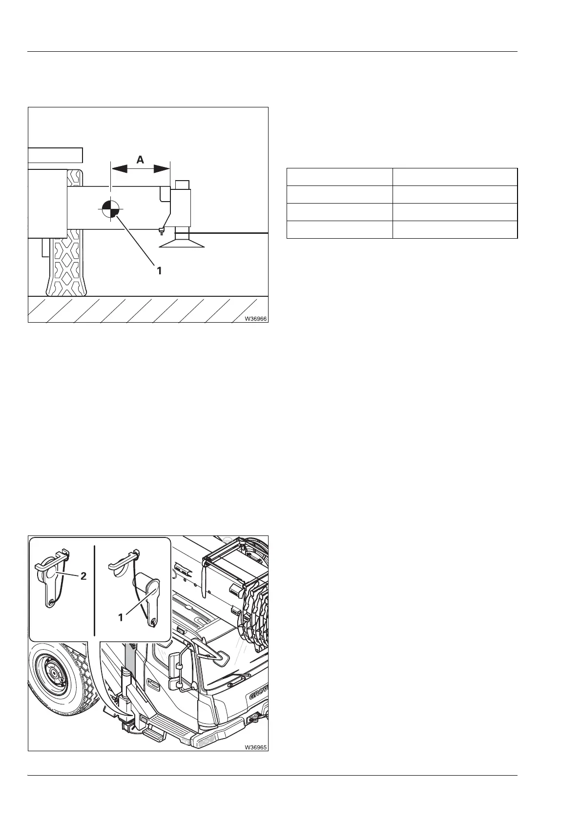
6.5.3 Centre of gravity data
The information in this section relates to a
fully retracted outrigger beam package.
The centre of gravity is defined by the
distance (A).
6.5.4 Preparations – for removal
Labelling the outrigger beams
Each outrigger beam is designed for just one installation point. If, for exam-
ple, you remove the outrigger beam on the rear left hand side, you must
mount the same outrigger beam on the rear left hand side again.
• Before you remove all outrigger beams for the first time, label them with
the correct installation point and if necessary, also with the serial number
of the truck crane.
Release the outrigger beams
All outrigger beams are retracted.
• Pull out the pin (1).
Lock the outrigger beams together
• Insert the pins (2).
Outrigger pads (A)
Without 860 mm (33.85 in)
Steel 825 mm (32.48 in)
Plastic 835 mm (32.87 in)

 Loading...


