UNDERCARRIAGE TMS700E SERVICE MANUAL
8-22 Published 01-29-2015, Control # 512-01
Mounting the Wheels on the Rear Axle
NOTE: Do not lubricate the wheel studs or lug nuts or the
wheel face or the hub. On aluminum wheels,
lubricate the wheel pilot or hub pads only with an
antiseize compound or synthetic lubricant with
teflon. Do not lubricate wheel or hub faces.
1. Raise the crane on outriggers so the rear wheels are off
the ground.
2. Generously coat the wheel pilot or hub pads with
antiseize compound. Do not apply antiseize compound
to the face of the wheel or the hub.
3. Place the inside steel wheel assembly on the mounting
studs. Take care not to damage the studs. Verify the
valve extension is in place on the inside wheel
assembly.
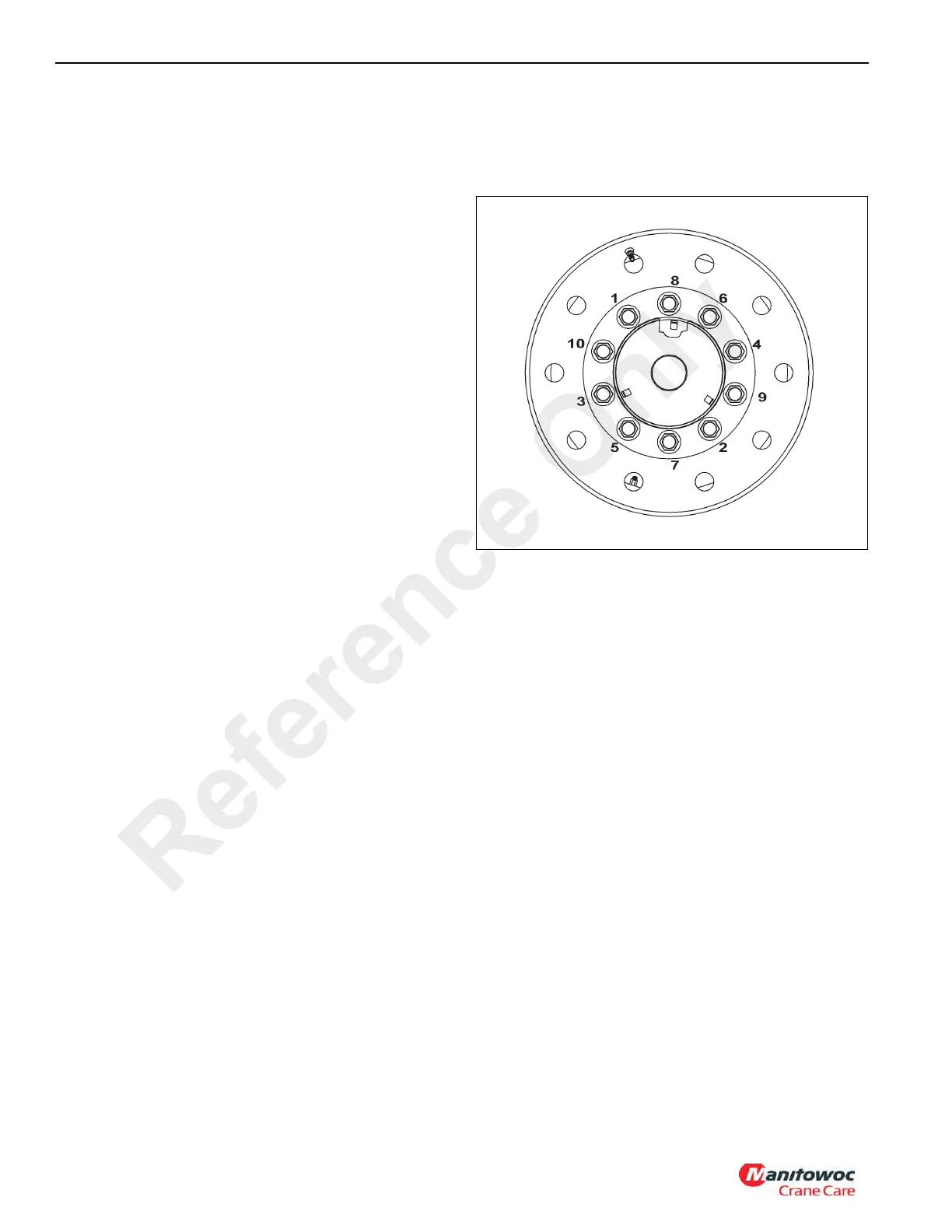
4. Align the outside aluminum wheel assembly so the valve
extension from the inside tire can fit through the hole
provided for it. (In Figure 8-14, the hole in question is
between the stud labeled “5” and the stud labeled “7”.
Place the outside wheel assembly on the mounting
studs. Take care not to damage the studs.
5. Place three spring clips (mounted evenly on the axle
flange) with the fingers extending inward toward the
wheel base. Slide hub cover over clips.
6. Install the lug nuts and tighten them until they are just
snug. Rotate the wheels while installing each nut so the
nut being tightened is in the top position. Do not lubricate
the nuts or studs.
7. Slide the valve stem stabilizer over the valve extension
and press it into its hole in the wheel. The stabilizer
should be against the wheel surface when properly
installed.
8. Tighten the lug nuts in the sequence shown to a
preliminary torque of 68 Nm (50 lb-ft) (see Figure 8-14).
9. Keep tightening the lug nuts in the sequence shown until
all 10 are torqued to 610 to 678 Nm (450 to 500 lb-ft)
(see Figure 8-14).
10. Lower the crane onto its tires. Retract and stow the
outrigger assemblies and the floats.
11. Road-test the tire, then retorque to 610 to 678 Nm (450
to 500 lb-ft).
Maintain proper torque on wheel lugs and check for proper
wheel mounting. Retorque the lug nuts 80 to 160 km (50 to
100 miles) after the wheels are removed and reinstalled. This
will reseat the lug nuts. Check the torque every 800 km
(500 miles) thereafter.
Reference Only

 Loading...


