UNDERCARRIAGE TMS700E SERVICE MANUAL
8-52 Published 01-29-2015, Control # 512-01
Reservoirs
Six air reservoirs store compressed air for braking and
auxiliary air devices. The first reservoir in the system (front
primary supply) also acts as a purge tank to remove
additional moisture not removed by the air dryer. It contains
an automatic drain valve. The other five reservoirs have a
manual drain valve actuated by a cable lanyard accessible
from the outside of the carrier.
Low Pressure Indicator Switches
The low pressure indicator switches (see Figure 8-57) are
used to warn the operator of low pressure in the air systems.
One switch is installed in each system and they are
electrically connected in parallel to illuminate the Air
Pressure Low Indicator on the front console in the cab.
Observe the dual air pressure gauge to determine which
system is low. The switch contacts close when the pressure
in the system decreases to 5.17 bar (75 psi).
Stop Light Switch
The stop light switches (see Figure 8-58) are installed in the
ports of the dual brake valve and are used to illuminate the
stop lights on the rear of the carrier when the brakes are
applied. There is one switch in each system (primary and
secondary) and they are connected electrically in parallel.
Air Pressure Gauge
The dual air pressure gauge is located on the left side of the
front console. The gauge is a direct reading pressure gauge
with two indicating pointers, red for the primary system and
green for the secondary system. The gauge has a dual scale
calibrated from 0 to 150 psi and 1.00 to 10.00 bar.
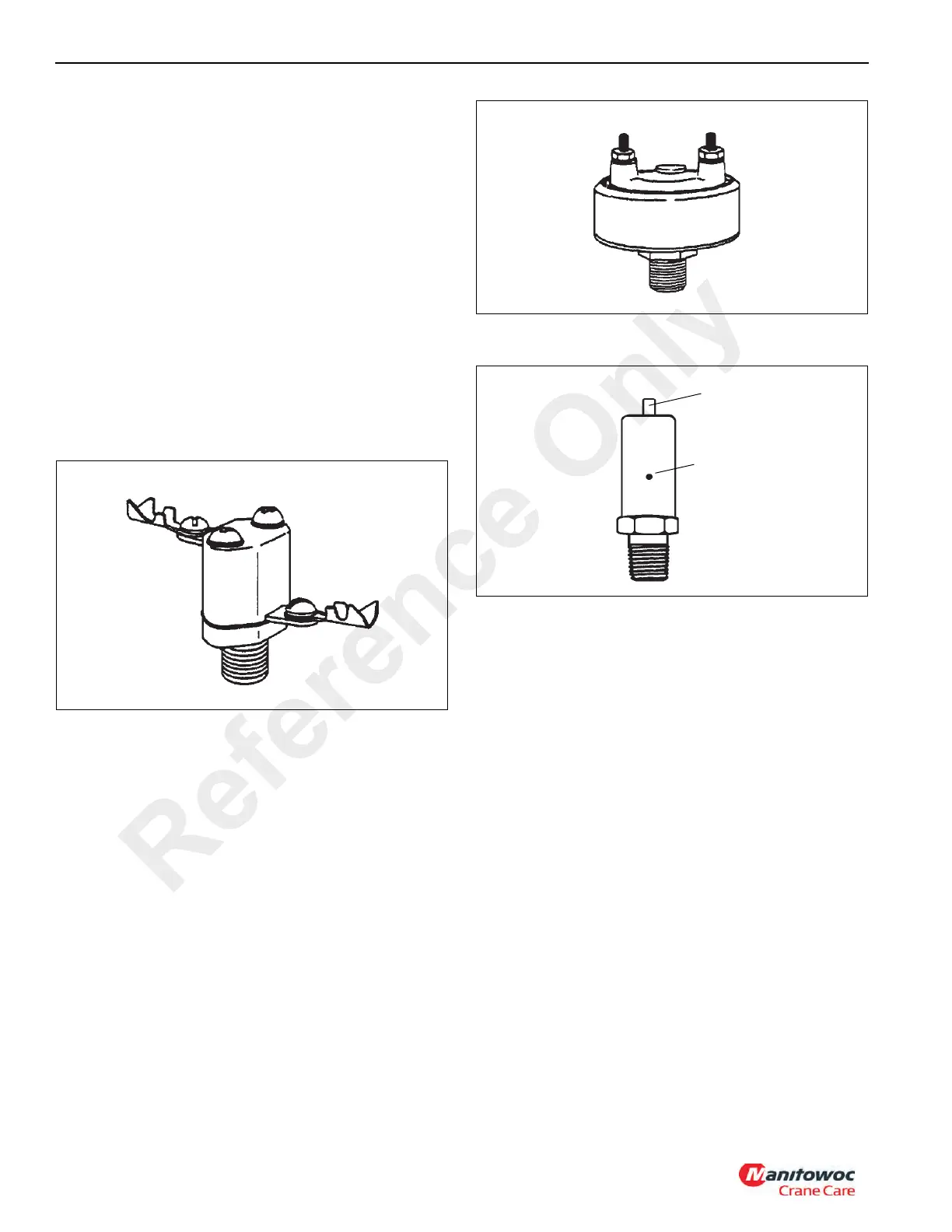
Safety Valve
A safety valve (see Figure 8-59) is installed in the primary
(front) supply reservoir to protect the air system against
excessive air pressure buildup. The valve consists of a
spring loaded ball which exhausts the system if the pressure
rises above 10.30 bar (150 psi). A second safety valve is
installed in the tire inflation circuit and is set at 12.07 bar (175
psi).
Automatic Drain Valve
The automatic drain valve (see Figure 8-60) is located in the
bottom of the primary (front) supply reservoir and is designed
to collect and eject moisture and contaminates from the
reservoir. The valve is operated by a difference in air
pressure between the tank and valve sump cavity. If the
pressure in the tank is greater than in the sump cavity, the
inlet valve opens and drains moisture into the sump cavity. If
the sump cavity pressure is greater than the tank pressure,
the exhaust valve opens and expels the moisture to the
outside. Both valves are closed when the pressure is
equalized.
Exhaust
Port
Release
Pin
FIGURE 8-59
Reference Only

 Loading...


