UNDERCARRIAGE TMS700E SERVICE MANUAL
8-68 Published 01-29-2015, Control # 512-01
9. Connect the hydraulic lines as tagged prior to removal.
10. Install the side adjustable wear pad in the outrigger box.
11. Adjust the wear pads, refer to Wear Pad Adjustment,
page 8-69.
12. Install the end and top box covers.
NOTE: At installation, be sure that the outrigger jack
cylinder hydraulic hoses are not trapped against
the outrigger box when the beam is fully retracted.
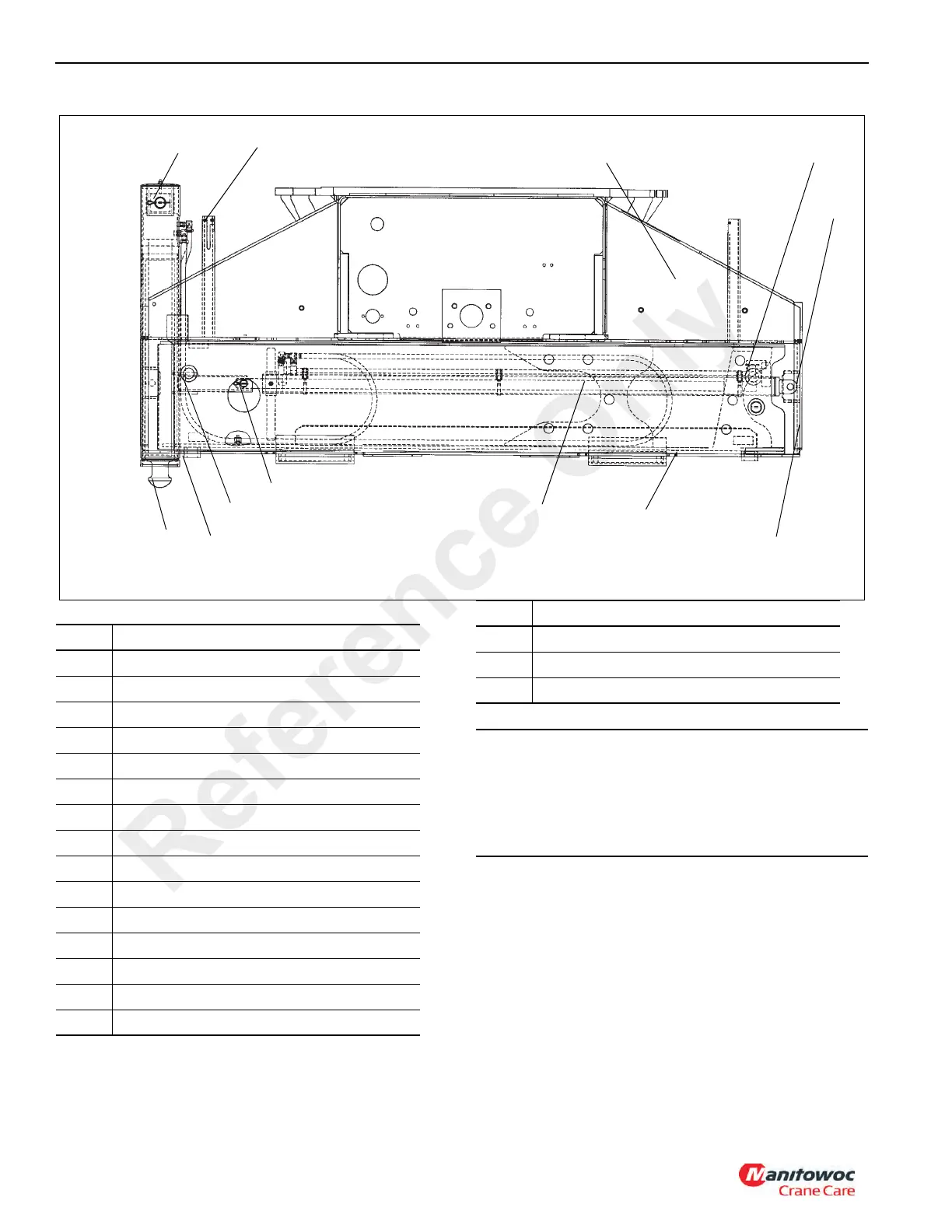
1,2
3
4
7
5, 6
8, 9, 10, 11
12
13
5, 6
16, 17
18
14, 15
FIGURE 8-65
Item Description
1 Retainer Pin
2 Cotter Pin
3 Mid Extension Lock
4 Outrigger Box
5 Clevis Pin
6 Cotter Pin
7 Tubing Clamp
8 End Cover Plate
9 Retainer Nut
10 Capscrew
11 Washer
12 Outrigger Beam
13 Extension Cylinder
14 Side Wear Pad
15 Setscrew
16 Lower Front Wear Pad
17 Setscrew
18 Jack Cylinder
CAUTION
During initial start-up and checking of the outrigger
operation, each control switch must be operated before
operating the selector valve. If hydraulic lines are
reversed to one or more cylinders, this will prevent
damage to the cylinders.
Item Description
Reference Only