a - Electronic throttle control (throttle position sensor)
b - Oil temperature sensor
c - Oil pressure sensor
d - Block water pressure sensor
e - Camshaft position sensor
f - Exhaust gas temperature sensor
g - Intake air temperature sensor
h - Engine coolant temperature sensor
i - Water‑in‑fuel sensor
j - Shift actuator (shift position sensor)
k - Shift demand sensor (signal A)
l - Throttle demand sensor (signal A)
m - Propulsion control module connector C
n - Propulsion control module connector B
Circuit Description
PCM sensor power A (XDRP1) supplies 5 volts to the sensors identified on the preceding diagram. On mechanical models, the
purple and yellow wire from pin F1 of PCM connector C connects to splices 101A and 101B, which feed all seven identified
sensors.
PCM sensor ground A (XDRG1) connects all twelve identified sensors to ground through the PCM (pin E1 of connector C). The
black and orange ground circuit incorporates three splices (100A, 100B, and 100C).
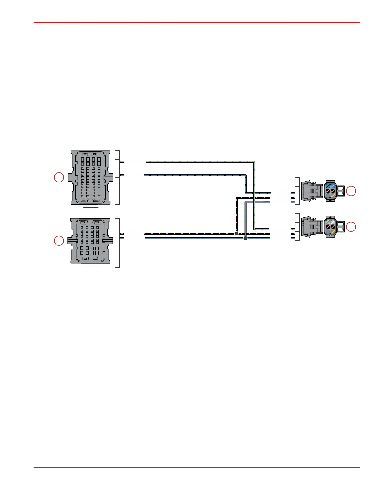
Sensor Power B
a - Shift demand sensor (signal B)
b - Throttle demand sensor (signal B)
c - Propulsion control module connector C
d - Propulsion control module connector B
Circuit Description
Sensor power B is used only on mechanical models.
PCM sensor power B (XDRP2) supplies 5 volts to the sensors identified on the preceding diagram. The purple and green wire
from pin F2 of PCM connector C connects to splice 118A, which feeds both identified sensors.
PCM sensor ground B (XDRG2) connects both identified sensors to ground through the PCM (pin E2 of connector C). The
black and pink ground circuit incorporates a single splice (116).
116
118A
BLK/PNK
PPL/GRN
GRA/GRN
GRA/GRN
BLU/BLK
PPL/GRN
PPL/GRN
BLK/PNK
BLK/PNK
BLU/BLK
A1
E2
F2
H4
A1
J1
K2
M4
A
B
C
D
E
F
A
B
C
D
E
F
A B
C
D E F G H
J
K
AB
C
DEFGH
J
K
1
3
2
4
L
M
L
M
Sensors
90-8M0146617 eng JULY 2018 © 2018 Mercury Marine Page 5A-9
 Loading...


