DMT 2004 Digital Multimeter 91‑892647A01
A
C O
M
m
A
V H z
mV
V
H z TEMP
m A
A
IG
IP
OFF
H z
TEMP
4516
Measures RPM, ohms, amperes, AC and DC voltages; records maximums and
minimums simultaneously, and accurately reads in high RFI environments.
Ignition Coils
The primary (+) side of the ignition coil receives battery voltage from the main power relay. When the key switch is turned ON,
the main power relay ground circuit is completed through the PCM. The main power relay transfers battery voltage to the coils.
The coils are protected by a 20‑amp fuse. The negative side of each coil is connected to the engine ground through the PCM.
When this circuit is closed, a magnetic field is built up in the ignition coil. When the PCM is supplied with a trigger signal, the
PCM opens the circuit and the magnetic field collapses across the coil secondary winding, creating a high voltage charge that
is sent to the spark plugs. Each coil supplies spark to two cylinders. The ignition system is a wasted spark design, where each
coil fires once every revolution.
Ignition Coil Test ‑ CDS G3
The ignition coils can be tested with the CDS G3 diagnostic interface tool. Follow the on‑screen instructions in CDS G3.
CDS G3 Interface Kit
8M0138392
Spark Gap Tester 91‑850439T 1
Ignition Coil Tests ‑ Digital Multimeter
DMT 2004 Digital Multimeter
91‑892647A01
NOTE: Refer to the wiring diagram, following.
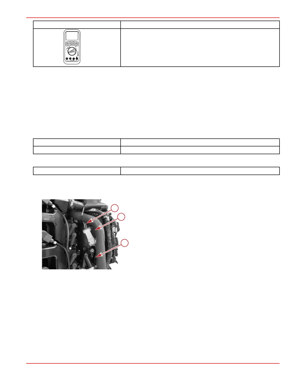
1. Cut the cable tie that secures the coil harness, and disconnect the coil harness from the side of the engine harness.
2. Remove the coil harness connector from the anchor on the electrical panel.
a - Coil harness
b - Side of the electrical panel
c - Engine harness
3. Perform a visual inspection of the pins and sockets on the connectors. Look for loose, broken, bent, or corroded pins.
4. Use a DMT 2004 digital multimeter to perform the following tests:
a. Set the meter to DC volts, turn the ignition key switch on, and check for battery voltage between socket E of the
engine harness connector and chassis ground. If voltage is not present, then there is an open somewhere in the
positive circuit from the hot stud to socket E of the connector. Refer to the wiring diagram, following.
b. With the meter still set to DC volts and the ignition key still on, check for battery voltage between socket E and each
of the other sockets in the connector. If voltage is not present for a pin, then there is an open between that socket and
the PCM.
c. Turn off the ignition key and change the meter to ohms. Measure the resistance between pin E of the coil harness
and each of the other pins. The resistance should be approximately that of the primary coil (0.3–0.5 ohms).
Ignition
90-8M0146617 eng JULY 2018 © 2018 Mercury Marine Page 6A-3
 Loading...


