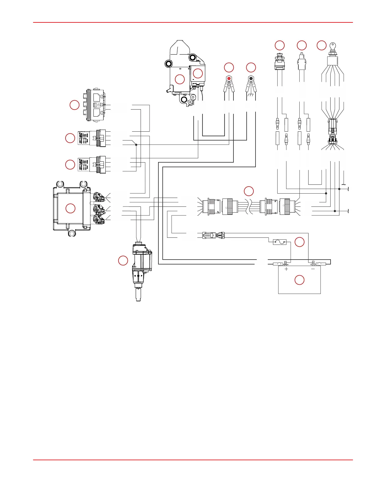
Starting System Components and Connections ‑ Mechanical
Typical mechanical engine controls
a - Propulsion control module (PCM)
b - Start relay
c - Main power relay (MPR)
d - Fuse block ‑ 20‑amp fuse used for the start circuit
e - Starter motor
f - Starter solenoid
g - Hot stud
NOTE: RED* indicates a black cable with red sleeves at the ring terminals.
h - Chassis ground stud
i - E‑stop switch (lanyard type shown)
j - Neutral start switch (typically integral to the remote control)
k - Ignition key switch (typical)
l - 14‑pin data harness (engine to helm)
m - Clean power harness with 5‑amp fuse
n - Engine starting battery
o - Shift actuator
YEL/RED
RED
RED
YEL/PPL
RED/WHT
RED
RED/BLU
BLK/BLU
YEL/RED
RED/WHT
RED/BLU
BLK/BLU
YEL/PPL
BLK/YEL
PPL
YEL/RED
RED
BLK
BLK/YEL
PPL
PPL/WHT
YEL/RED
YEL/RED
YEL/RED
RED
BLK
BLK/YEL
PPL
PPL/WHT
GRN
PNK
BLK/YEL
PPL
YEL/RED
RED/BLK
BLK
YEL/RED
RED*
RED*
RED
RED*
RED/BLK
BLK
RED*
YEL/RED
YEL/RED
RED
BLK
BLK/YEL
PPL
BLK
BLK
BLK
BLK
BLK
BLK BLK/YEL
BLK
Charging and Starting System
90-8M0146617 eng JULY 2018 © 2018 Mercury Marine Page 6B-11
 Loading...


