3. Cut the cable tie that secures the electrical connector bundle below the electrical plate, locate the EGT sensor harness,
and disconnect it from the engine harness.
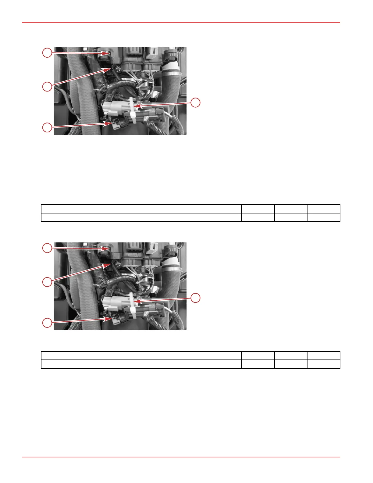
a - Electrical panel
b - Cable tie
c - EGT sensor connector (location varies)
d - EGT sensor
4. Remove the top two T30 Torx screws and washers securing the electrical plate to the exhaust tube.
5. Slide the electrical plate upward to gain additional access to the EGT sensor.
6. Remove the EGT sensor from the exhaust tube.
EGT Sensor Installation
1. Ensure that the O‑ring is in good condition and is present on the sensor.
2. Install the EGT sensor into the exhaust tube.
3. Tighten the sensor to the specified torque.
Description
Nm lb‑in. lb‑ft
EGT sensor 15 132.8 –
4. Connect the sensor harness to the engine harness.
5. Secure the electrical connector bundle with a cable tie.
a - Electrical panel
b - Cable tie to secure electrical connector bundle
c - EGT sensor connector (location varies)
d - EGT sensor
6. Slide the electrical panel into position, and secure it to the exhaust tube with two T30 Torx screws and washers. Tighten
the screws to the specified torque.
Description
Nm lb‑in. lb‑ft
T30 Torx screws 10 88.5 –
Intake Air Temperature (IAT) Sensor
The intake air temperature (IAT) sensor is a thermistor that is inserted into the incoming air stream, immediately before the fuel
injectors. The PCM receives the data from the IAT, and adjusts the fuel injection duration needed to run the engine at optimum
efficiency. When intake air is cold, the sensor resistance is high. As the air temperature rises, resistance lowers. Outside air
temperature directly affects the engine intake air temperature.
Sensors
Page 5A-22 © 2018 Mercury Marine 90-8M0146617 eng JULY 2018
 Loading...


