Special Tools
CDS G3 Interface Kit 8M0138392
CDS G3 license key, interface, adapter, and harness
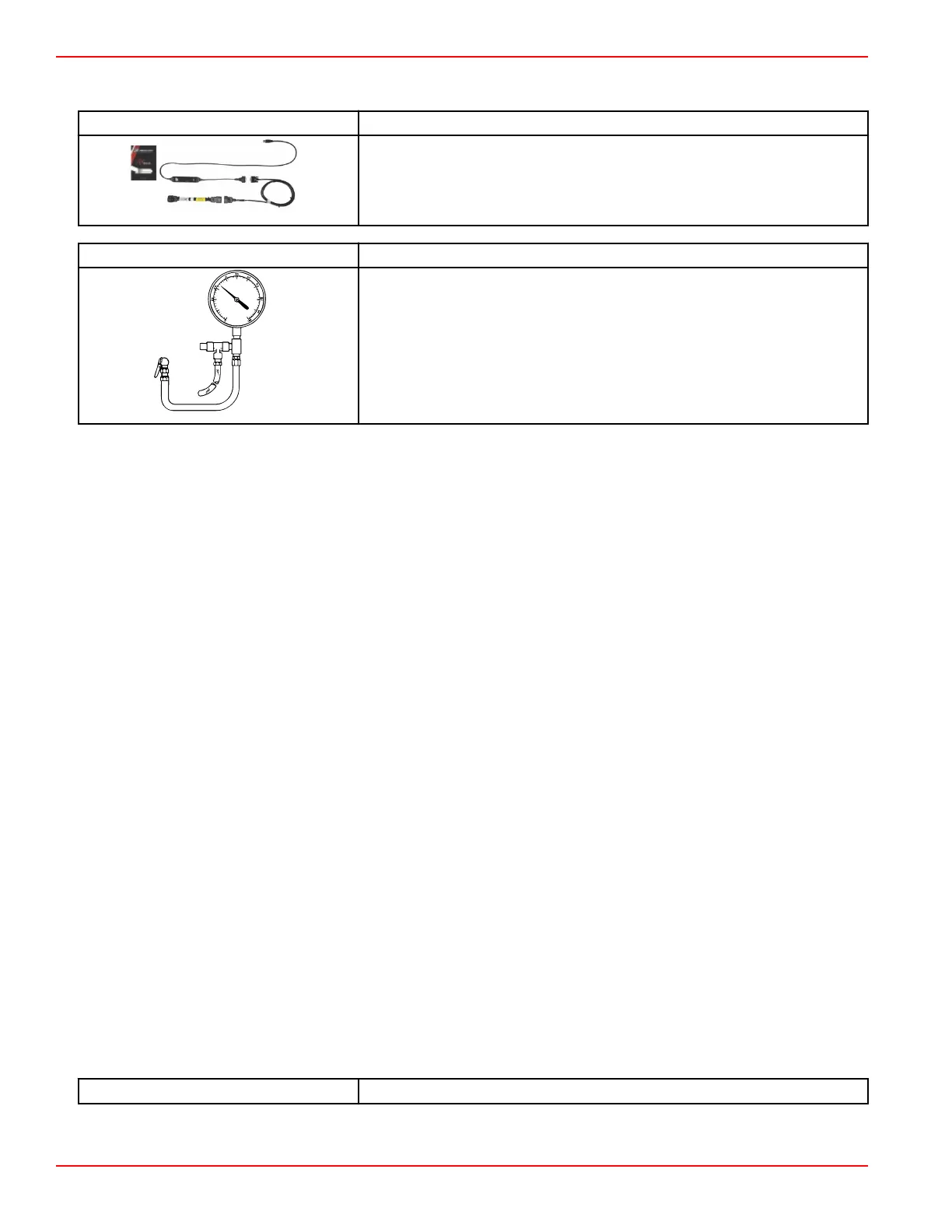
Fuel Pressure Gauge Kit 91‑881833A03
Tests the fuel pump pressure; can be used to relieve fuel pressure.
Fuel Component Troubleshooting and Diagnostics
Antisiphon Valves
Antisiphon valves can be helpful from a safety standpoint, however, they can clog with debris, may be restrictive, or have too
heavy a spring. The pressure drop across these valves can create operational problems and/or powerhead damage by
restricting fuel to the fuel lift pump, and the high‑pressure fuel pump. Some symptoms of restricted (lean) fuel flow, possibly
caused by use of an antisiphon valve, are:
• Severe fuel rail pressure fluctuation
• Loss of fuel pump pressure
• High‑speed surging
• Outboard cuts out or hesitates upon acceleration
• Outboard runs rough
• Outboard quits and cannot be restarted
• Outboard will not start
• Vapor lock
Antisiphon valves are typically installed between the fuel tank outlet and the engine fuel inlet. Use an alternative fuel supply,
such as a remote tank, to determine if bad fuel or a malfunctioning antisiphon valve is causing the problem.
If it is found that the antisiphon valve is the cause of the problem, replace the antisiphon valve with one that has a lighter spring
tension, or replace it with a solenoid‑operated fuel shutoff valve.
Fuel Supply Module (FSM)
The fuel supply module (FSM) that contains the fuel lift pump and the high‑pressure fuel pump is energized by a 12‑volt circuit
that is controlled by the fuel pump relay (FPR). When the key switch is turned to the ON position, the PCM activates the FPR to
energize the FSM for approximately three seconds before the engine is started. When the PCM receives a signal from the
crankshaft position sensor, the FPR is activated again, and the FSM runs continuously until the key switch is turned off. The
fuel pump circuit is protected by a 20‑amp fuse.
If fuel starvation is indicated, verify high‑pressure pump operation by testing the lift pump with a vacuum gauge and checking
fuel pressure on one of the fuel rails. The fuel pump circuit can be activated using the CDS G3 diagnostic interface tool.
Fuel Lift Pump
The fuel lift pump and high‑pressure pump are on the inside of the fuel supply module. The fuel lift pump cannot be electrically
tested separately from the high‑pressure pump when installed as part of the fuel supply module assembly. The fuel lift pump
can be tested for operation electrically with the CDS G3 diagnostic interface tool.
CDS G3 Interface Kit
8M0138392
NOTE: This test should be completed during engine idle or light load operation. If no fuel demand exists and the FSM is filled,
the lift pump will not pull fuel to create a vacuum. At engine idle, inlet vacuum may build slowly.
Troubleshooting and Diagnostics
Page 7B-2 © 2018 Mercury Marine 90-8M0146617 eng JULY 2018
 Loading...


