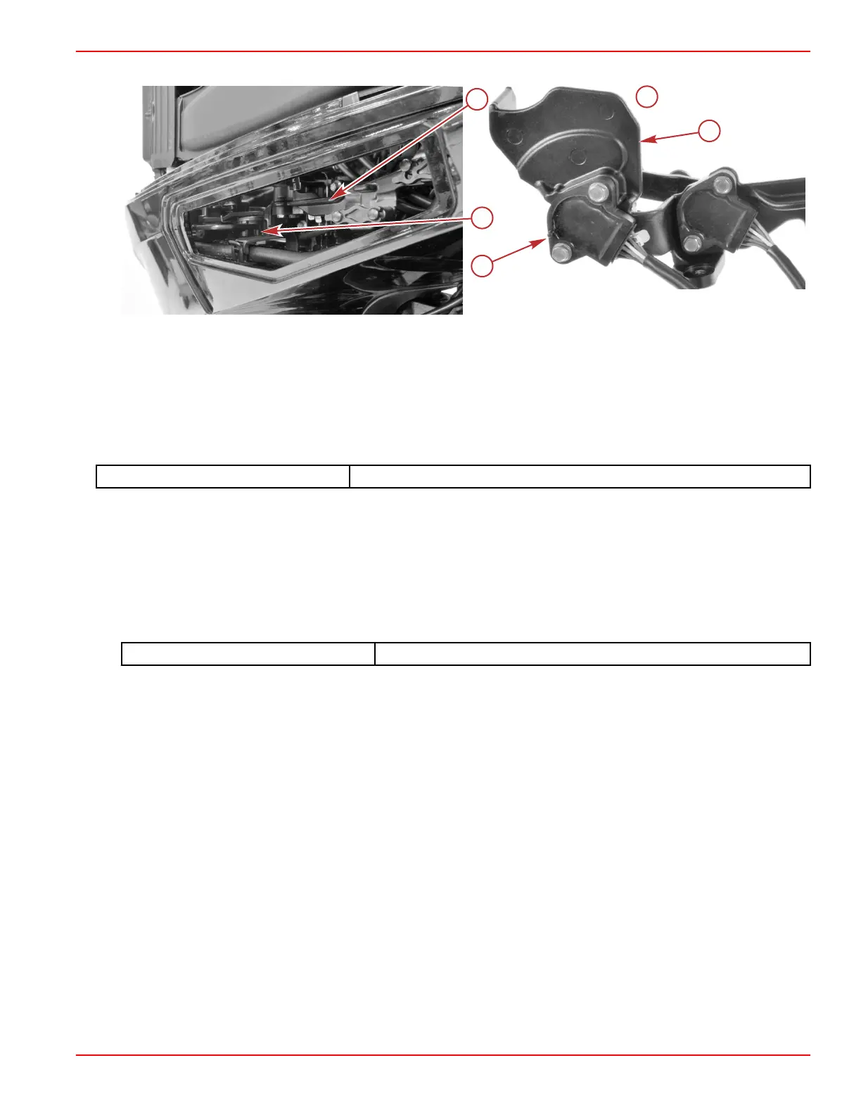
The throttle demand sensor is the aftmost of the two sensors on the throttle and shift bracket.
a - Throttle and shift bracket
b - Throttle demand sensor
c - Underside of throttle and shift bracket (removed from engine)
Throttle Demand Sensor Testing
Monitor the operation of the throttle demand sensor by viewing the DemandLinear data item on the CDS G3 Live Data screen.
The value of this data item should rise and fall (as a percent) with the movement of the operator throttle control.
CDS G3 Interface Kit
8M0138392
If the value of DemandLinear does not change as the throttle control is moved, shake or move the sensor harness and
connector. If the value of DemandLinear begins to change, look for a broken, loose, or corroded wire.
Continue testing with the engine OFF:
1. Disconnect the engine harness connector from the throttle demand sensor.
2. Visually inspect the sensor pins and the wires coming from the engine harness connector. Look for broken, bent, or
corroded pins at the sensor and loose, broken, or corroded wires at the engine harness connector.
3. Perform a continuity check of the sensor wiring in the engine harness, between the sensor connector and the PCM. Note
that there are splices in both the power and ground circuits.
DMT 2004 Digital Multimeter
91‑892647A01
Sensors
90-8M0146617 eng JULY 2018 © 2018 Mercury Marine Page 5A-41
 Loading...


