Connection to the Junction Box or Diagnostic Port
1. Insert the CDS G3 SmartCraft diagnostic interface USB connector into a powered USB port.
2. Connect the SmartCraft diagnostic interface 9‑pin connector to the CAN P/CAN H adapter harness 9‑pin connector.
3. Connect the CAN P/CAN H adapter harness to the junction box or diagnostic port.
IMPORTANT: Ensure that the correct termination resistors are installed on the CAN P and CAN H buses. The CAN P and
CAN H buses must be properly terminated for the tool to communicate. Improper termination will result in communication
errors or complete loss of communication.
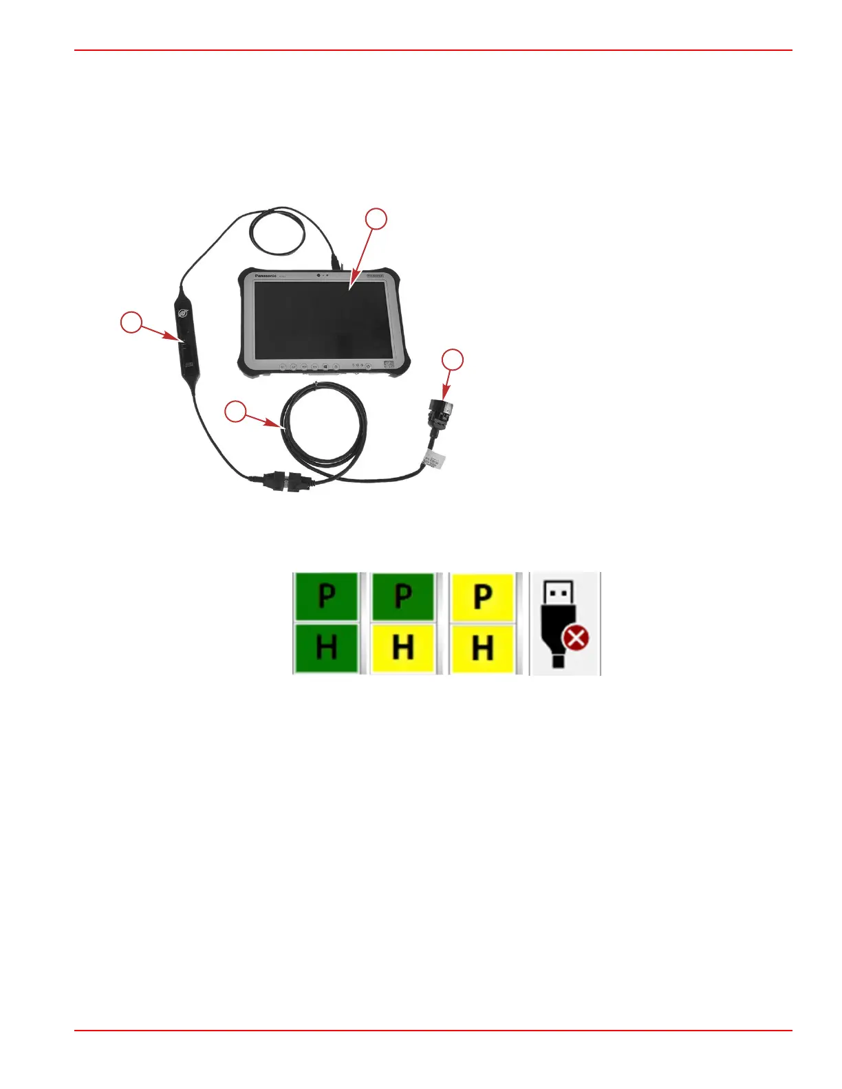
a - Tablet/computer
b - CDS G3 SmartCraft diagnostic interface
c - CAN P/CAN H adapter harness
d - Connect to junction box or diagnostic port
Starting CDS G3
With the CDS G3 computer correctly connected to the vessel's CAN P bus and the CDS G3 program running, turn the key to
the on position. The CAN P indicator should turn green, indicating that CAN traffic exists between the PCM and the computer.
CAN traffic indicators
The CAN indicators will let you know the communication status on CAN P and CAN H.
Green—The computer is communicating on the CAN bus.
Yellow—The computer is communicating with the cable but no data is being received on the CAN bus.
Red X—The computer is not connected to the SmartCraft diagnostic interface cable.
If CDS G3 Does Not Communicate with the System
Is the CDS G3 CAN P traffic indicator icon red or yellow? If it is red, the SmartCraft diagnostic interface is not connected,
not recognized by Windows®, or not configured correctly in the CDS G3 options menu. This is not a CAN issue, but rather a
computer issue.
Improper installation of CDS G3 driver software can result in disabling a USB port from communicating with the CDS G3
diagnostic cable. Try moving the CDS G3 diagnostic interface cable from the current USB port to an alternative port to see if
this resolves the red CAN P/CAN H.
If the indicator is yellow, the SmartCraft diagnostic interface is connected and communicating with the CDS G3 program
through the USB port, but it is not communicating with the CAN bus. Ensure that the key switch is in the on position and that
the proper termination resistance is being used.
Is the SmartCraft diagnostic interface’s PWR LED illuminated continuously? This indicates the cable is recognized by the
computer and is communicating with the computer.
Troubleshooting with the Computer Diagnostic System (CDS G3)
90-8M0146617 eng JULY 2018 © 2018 Mercury Marine Page 3B-3
 Loading...


