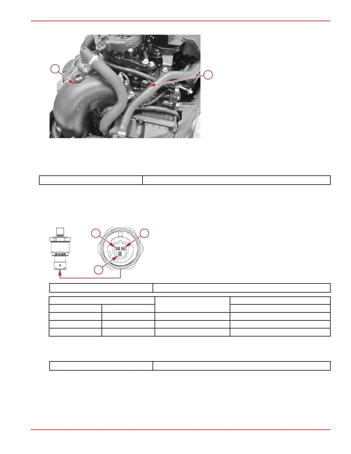
The block water pressure sensor, if equipped, is located on the top aft of the engine, near the exhaust manifold.
a - Exhaust manifold
b - Block water pressure sensor
Block Water Pressure Sensor Tests
Monitor the pressure (data item SeaPumpPress) on the CDS G3 Live Data screen. If the block water pressure sensor does
not appear to indicate a pressure change when engine RPM is varied, shake or move the sensor harness and connector. If the
pressure begins to change, look for a broken, loose, or corroded wire.
CDS G3 Interface Kit
8M0138392
Continue testing with the engine OFF:
1. Disconnect the engine harness connector from the sensor.
2. Visually inspect the sensor pins and the wires coming from the engine harness connector. Look for broken, bent, or
corroded pins at the sensor and loose, broken, or corroded wires at the engine harness connector.
3. Measure the resistance between pins A, B, and C of the block water pressure sensor.
a - Pin A – ground (–)
b - Pin B – power (+)
c - Pin C – pressure signal
DMT 2004 Digital Multimeter 91‑892647A01
Meter Test Leads
Meter Scale
Reading
Red Black At 21 °C (70 °F)
Pin A Pin B Auto 78.4–145.6 kΩ
Pin A Pin C Auto 182.0–338.0 kΩ
Pin B Pin C Auto 100.8–187.2 kΩ
4. Perform a continuity check of the sensor wiring in the engine harness, between the sensor connector and the PCM. Note
that there are splices in both the power and ground circuits.
NOTE: Sensor power splice numbers vary between DTS and mechanical models.
DMT 2004 Digital Multimeter
91‑892647A01
Sensors
90-8M0146617 eng JULY 2018 © 2018 Mercury Marine Page 5A-11
 Loading...


