3. Remove the two M5 x 16 hex washer head screws that secure the shift demand sensor to the underside of the throttle and
shift bracket, and remove the sensor.
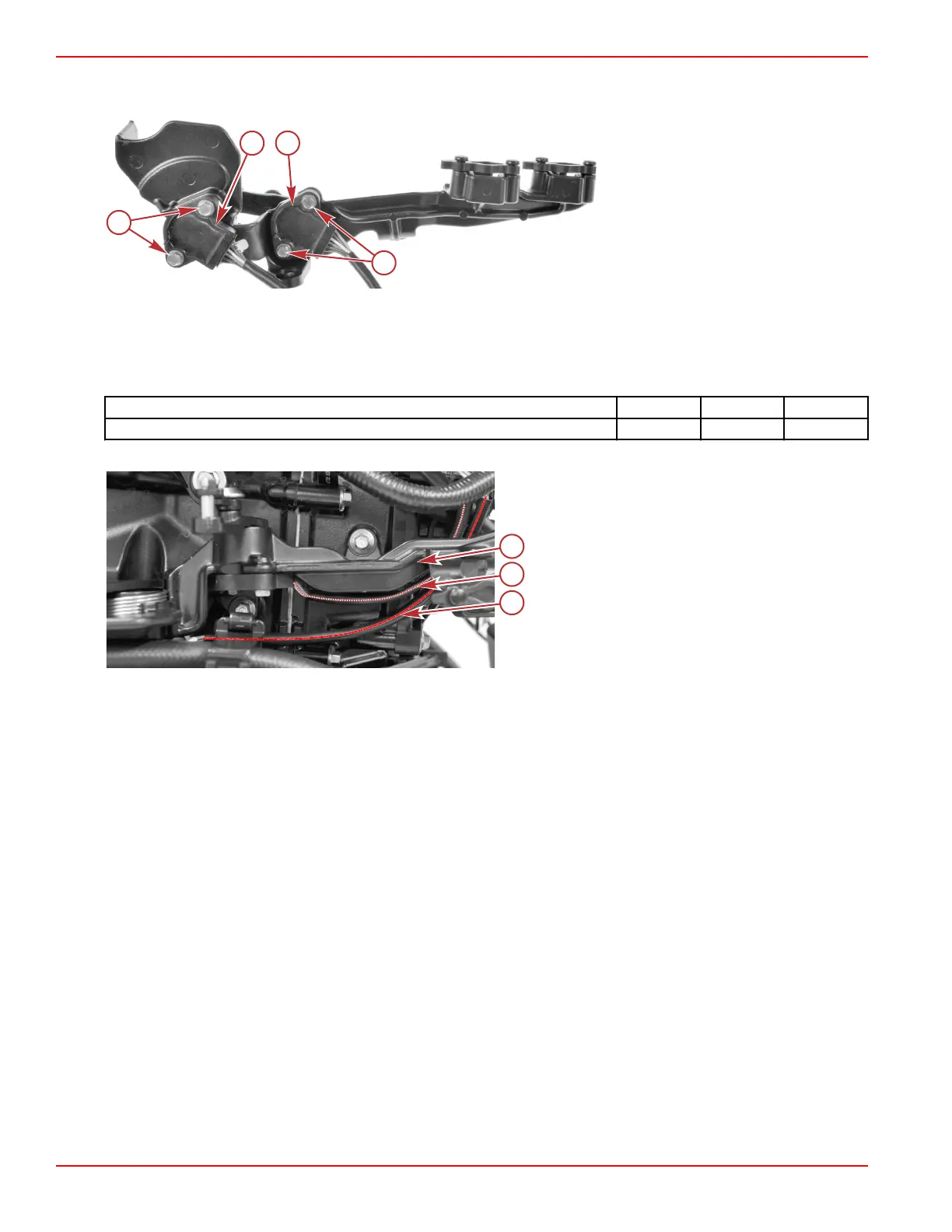
Throttle and shift bracket, shown
removed for clarity
a - M5 x 16 hex washer head screws (2
per sensor, 4 total)
b - Throttle demand sensor
c - Shift demand sensor
Shift Demand Sensor Installation
NOTE: Refer to previous illustrations as required.
1. Attach the shift demand sensor to the underside of the throttle and shift bracket, using two M5 x 16 hex washer head
screws. Tighten the screws to the specified torque.
Description
Nm lb‑in. lb‑ft
M5 x 16 hex washer head screw 1.7 15 –
2. Route the shift demand sensor harness between the throttle and shift bracket and the engine block.
a - Throttle and shift bracket
b - Shift demand sensor harness
c - Throttle demand sensor harness
3. Connect the shift demand sensor harness to the engine harness. Use a cable tie to secure the connection to the engine
harness.
Throttle Demand Sensor
NOTE: The throttle demand sensor is only on models with mechanical throttle and shift controls.
The demand sensors used for the throttle and shift demand are identical. They consist of two hall‑effect sensors in a single
housing, configured such that the value of the output signal of one sensor increases (from 0.5 VDC to 4.5 VDC) as the other
decreases (from 4.5 VDC to 0.5 VDC), and vice versa.
The sensors can be swapped for diagnostic purposes. Exercise special care to ensure that the sensor connections to the
engine harness are correct, prior to attempting to run the engine.
Sensors
Page 5A-40 © 2018 Mercury Marine 90-8M0146617 eng JULY 2018
 Loading...


