8. With the key switch in the START position, the starter drive should engage the engine flywheel. If not, turn off the key
switch, and measure the resistance between the yellow/red terminal on the starter solenoid and engine ground. If
resistance is not within specification, the starter solenoid is defective and must be replaced.
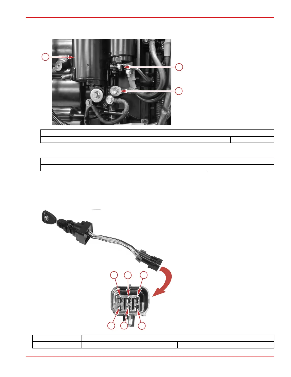
a - Starter motor
b - Starter solenoid yellow/red terminal
c - Engine ground
Starter Solenoid
Coil resistance (yellow/red terminal to ground) 0.2–0.4 Ω
9. If the starter drive audibly engages the engine flywheel, but the starter does not rotate, remove the starter and test the no
load current draw. If the current draw is not within specification, replace the starter assembly.
Starter
No load current draw 60–80 A
Key Switch Test (Four Position)
1. Disconnect the key switch from the command module harness.
2. Set ohmmeter on R x 1 scale for the following tests.
3. If meter readings are other than specified in the following tests, verify that the switch and not the wiring is faulty. If the
wiring checks OK, replace the switch.
a - Pin A ‑ Red
b - Pin B ‑ Black
c - Pin C ‑ Purple/white
d - Pin D ‑ Purple
e - Pin E ‑ Black/yellow
f - Pin F ‑ Yellow/red
Key Position Continuity should be indicated at the following points:
Off B E
Charging and Starting System
90-8M0146617 eng JULY 2018 © 2018 Mercury Marine Page 6B-13
 Loading...


