Terminal Test Probe Kit Bosch P/N MM‑ 46523
DTS model shown; mechanical
model similar
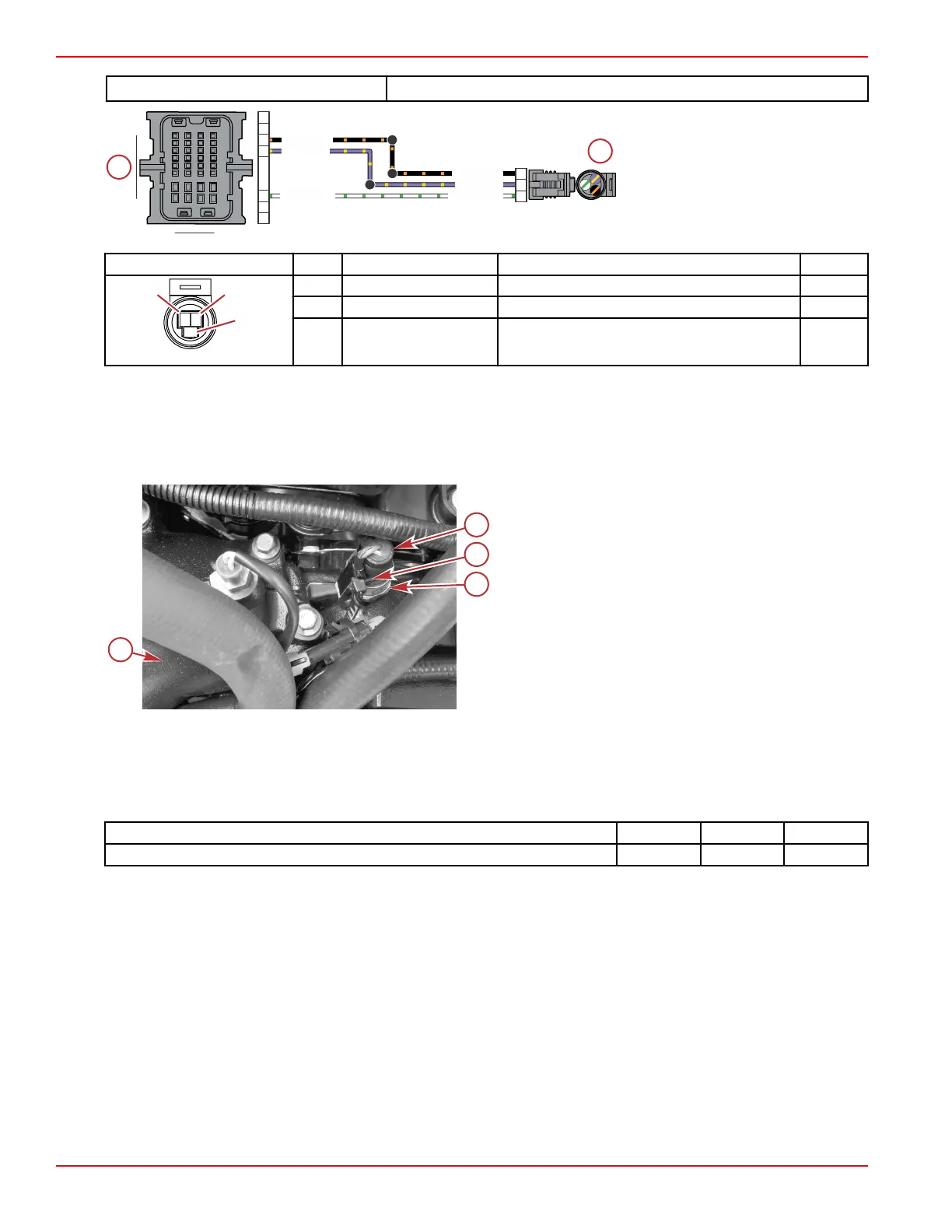
a - Block water pressure sensor
connector
b - PCM connector C
Connector Pin Wire Color Function PCM
A Black/orange Sensor ground A (–) CE1
B Purple/yellow Sensor power A (+) CF1
C White/green Block water pressure signal CB4
Block Water Pressure Sensor Removal
1. Cut the cable tie from the sensor's engine harness connector.
2. Disconnect the engine harness connector from the sensor.
3. Remove the sensor from the engine block.
a - Top of the exhaust manifold
b - Engine harness connector
c - Cable tie to secure the harness connection
d - Block water pressure sensor
Block Water Pressure Sensor Installation
1. Ensure that the O‑ring is in good condition and is installed on the sensor.
2. Install the block water pressure sensor into the engine block.
3. Tighten the sensor to the specified torque.
Description
Nm lb‑in. lb‑ft
Block water pressure sensor 15 132.8 –
4. Connect the engine harness to the sensor.
5. Secure the connection with a cable tie.
Camshaft Position Sensor
The camshaft position sensor supplies the PCM with cam timing and RPM information. When the camshaft position sensor is
functioning correctly, the PCM controls the fuel injection in a multiport timing strategy. The camshaft position sensor output to
the PCM changes from +5 volts to 0 volts throughout the engine rotation.
If the camshaft position sensor fails, the PCM will control the fuel injection in a batch fire strategy. The engine may not start as
quickly as normal. The PCM will generate and store a fault code, if the camshaft position sensor fails.
100A
100B
101A
PPL/YEL
PPL/YEL
WHT/GRN
WHT/GRN
BLK/ORN
BLK/ORN
A
B
C
A1
F1
E1
B4
H4
Sensors
Page 5A-12 © 2018 Mercury Marine 90-8M0146617 eng JULY 2018
 Loading...


