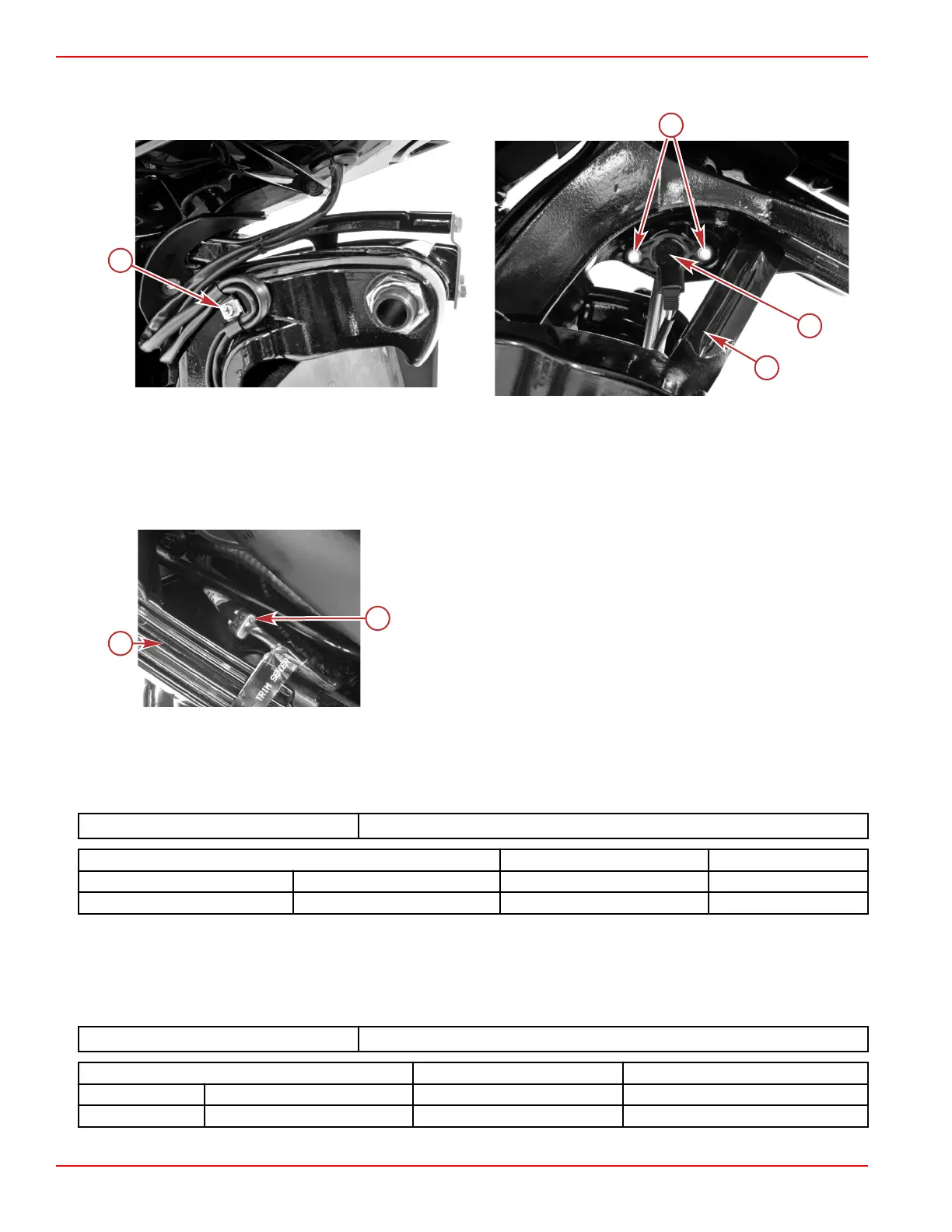
Trim Position Sensor Location
Conventional Midsection (CMS)
a - Screw
b - Screws (2)
c - Trim position sensor
d - Tilt lock lever
Trim position sensor connector
a - Port lower cowl
b - Trim position sensor connector
Testing the Trim Position Sensor Circuit with DMT 2004A
The trim position sensor requires a 5 volt reference signal from the PCM.
Check for reference signal voltage with the ignition switch in the RUN position and using an appropriate probe (paper clip, etc.)
inserted at the trim position sensor harness connector.
DMT 2004 Digital Multimeter
91‑892647A01
Meter Test Leads Meter Scale Reading
Red Black
Purple/black Black/green VDC 5.0 ± 0.1
If voltage is not as indicated or voltage is erratic, inspect the sensor wiring and connections.
IMPORTANT: The 5 volt reference at the PCM can be monitored by the CDS G3. Voltage should be 5.0 VDC ± 0.1 VDC. Any
other voltage indicates a defective PCM. If the PCM reference voltage is correct, but voltage at the trim sensor is low or
nonexistent, inspect the sensor wiring and connections.
Check the resistance of the trim position sensor circuit harness and PCM.
DMT 2004 Digital Multimeter
91‑892647A01
Meter Test Leads Meter Scale Reading
Red Black
Yellow Black/green Ohms 210 kΩ ± 20%
Conventional Midsection (CMS) Power Trim
Page 6C-14 © 2018 Mercury Marine 90-8M0146617 eng JULY 2018
 Loading...


