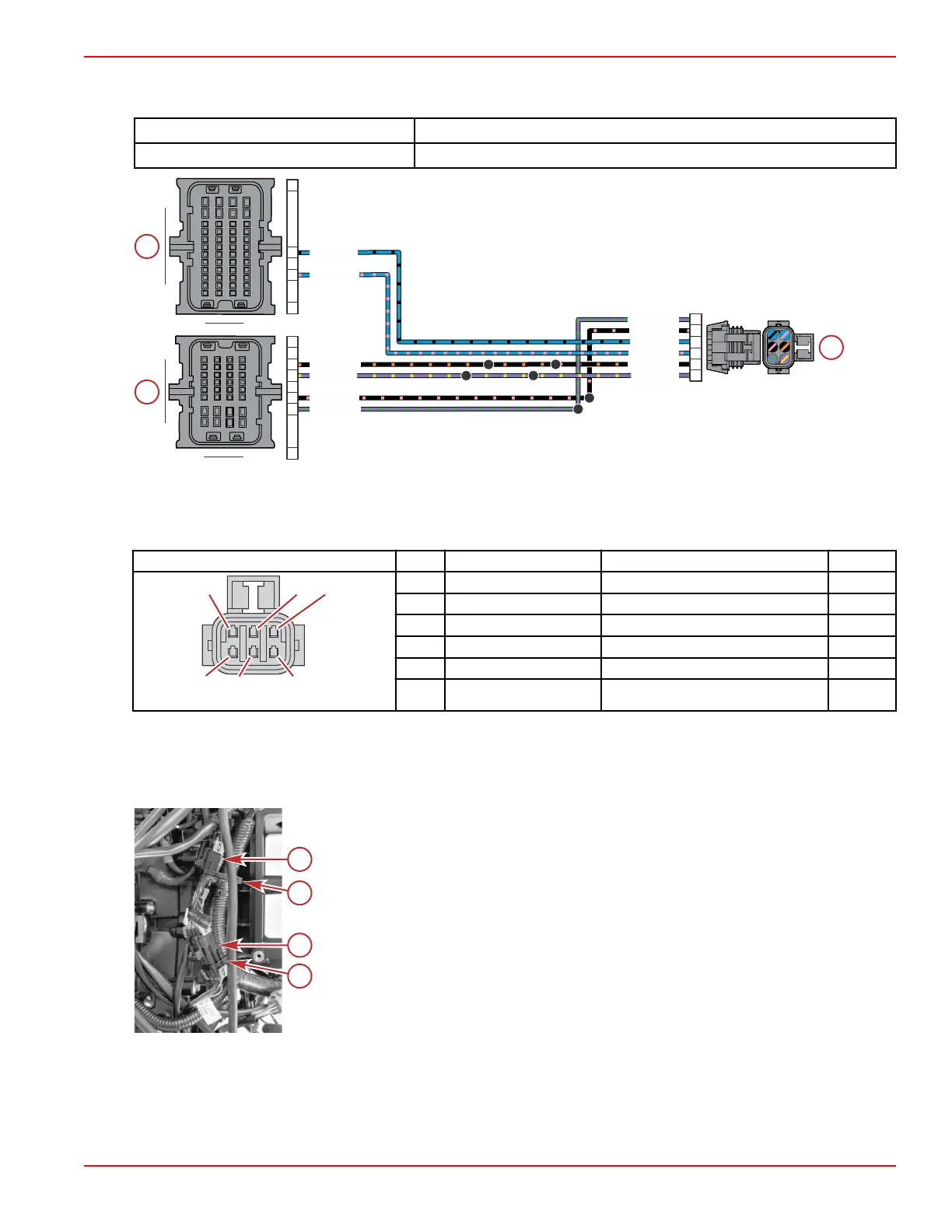
3. Perform a continuity check of the sensor wiring in the engine harness, between the sensor connector and the PCM. Note
that there are splices in both the power and ground circuits.
DMT 2004 Digital Multimeter 91‑892647A01
Terminal Test Probe Kit Bosch P/N MM‑ 46523
a - Shift demand sensor connector
b - PCM connector B
c - PCM connector C
Connector Pin Wire Color Function PCM
A Purple/green Sensor power B (+) CF2
B Black/pink Sensor ground B (–) CE2
C Blue/black Shift request 2 BK2
D Blue/pink Shift request 1 BK3
E Black/orange Sensor ground A (–) CE1
F Purple/yellow Sensor power A (+) CF1
Shift Demand Sensor Removal
1. Cut the cable tie that secures the shift demand sensor harness to the engine harness.
2. Disconnect the shift demand sensor harness from the engine harness.
a - Shift demand sensor connection
b - Cable ties (2)
c - Throttle demand sensor connection
S116
100C
100A
118
101B101A
PPL/YEL
BLK/ORN
BLK/ORN
BLK/PNK
PPL/GRN
BLU/BLK
BLU/PNK
PPL/GRN
BLK/PNK
BLU/PNK
BLU/BLK
PPL/YEL
A
B
C
D
E
F
H4
E1
F1
E2
F2
A1
K2
K3
M4
A1
A B
C
D E F G H
J
K
AB
C
DE
FGH
J
K
1
3
2
4
L
M
L
M
Sensors
90-8M0146617 eng JULY 2018 © 2018 Mercury Marine Page 5A-39
 Loading...


