Meter Test Leads
Meter Scale Reading
ETC connector pin PCM connector‑pin
1 C‑H2 Auto (Ω) Continuity
2 C‑H1 Auto (Ω) Continuity
3 B‑J4 Auto (Ω) Continuity
4 C‑F1 Auto (Ω) Continuity
5 B‑J2 Auto (Ω) Continuity
6 C‑E1 Auto (Ω) Continuity
• If any of the readings fail, then the problem is in the engine harness. Troubleshoot accordingly.
• If all of the readings are good, then the failure is most likely mechanical.
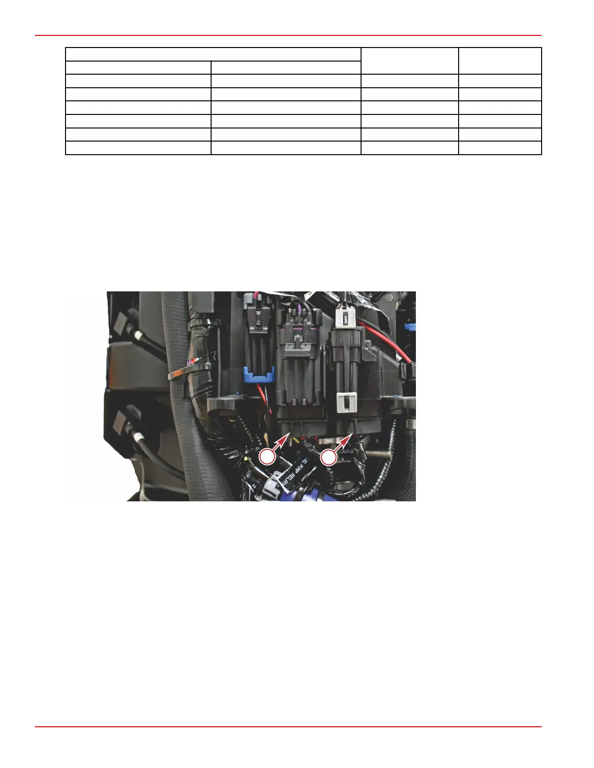
Fuel Pump Relay
The engine wire harness has a relay for fuel pump control, located on the electrical panel at the rear of the engine. The
incorporation of the fuel pump relay eliminates the possibility of pump damage when the key switch is turned to the ON position
and the fuel supply module (FSM) is empty of fuel. The fuel pump operation is indirectly controlled by the PCM. The PCM
completes the ground connection of the fuel pump relay, which in turn delivers power from the main power relay (MPR) to the
FSM. A 20‑amp fuse is in line with the power wire, between the MPR and the fuel pump relay. The fuel pump programmed logic
limits the initial fuel pump use at key ON for five seconds. After the initial five seconds, the fuel pumps will not be active until
engine RPM is recognized by the PCM.
a - Fuel pump relay
b - Starter relay
Actuators and Relays
Page 5B-4 © 2018 Mercury Marine 90-8M0146617 eng JULY 2018
 Loading...


