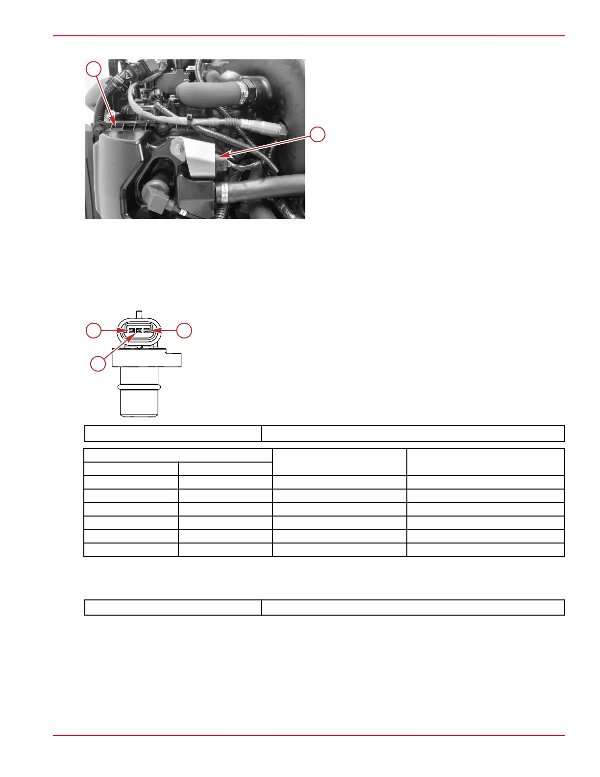
The camshaft position sensor is located at the top of the port valve cover.
a - Port valve cover
b - Camshaft position sensor
Camshaft Position Sensor Tests
1. Disconnect the sensor from the engine harness.
2. Perform a visual inspection of the sensor pins and the wires coming from the engine harness connector. Look for broken,
bent, or corroded pins at the sensor and loose, broken, or corroded wires at the connector.
3. If the pins and wiring appear serviceable, perform a resistance check on the sensor. Ensure that the resistance for the
camshaft sensor at 21 °C (70 °F) is within specification.
Camshaft position sensor
a - Pin A = output voltage
b - Pin B = ground
c - Pin C = reference voltage (5 V)
DMT 2004 Digital Multimeter 91‑892647A01
Meter Test Leads
Meter Scale Reading
Red Black
Pin A Pin B Auto 5.4 MΩ ± 30%
Pin A Pin C Auto 1.0 MΩ ± 30%
Pin B Pin A Auto 2.9 MΩ ± 30%
Pin B Pin C Auto 2.9 MΩ ± 30%
Pin C Pin A Auto 1.0 MΩ ± 30%
Pin C Pin B Auto 5.4 MΩ ± 30%
4. Perform a continuity check of the sensor wiring between the sensor connector and the PCM. Note that there are splices in
both the power and ground circuits.
NOTE: Sensor power splice numbers vary between DTS and mechanical models.
DMT 2004 Digital Multimeter
91‑892647A01
Sensors
90-8M0146617 eng JULY 2018 © 2018 Mercury Marine Page 5A-13
 Loading...


