Charging System
Charging System Components
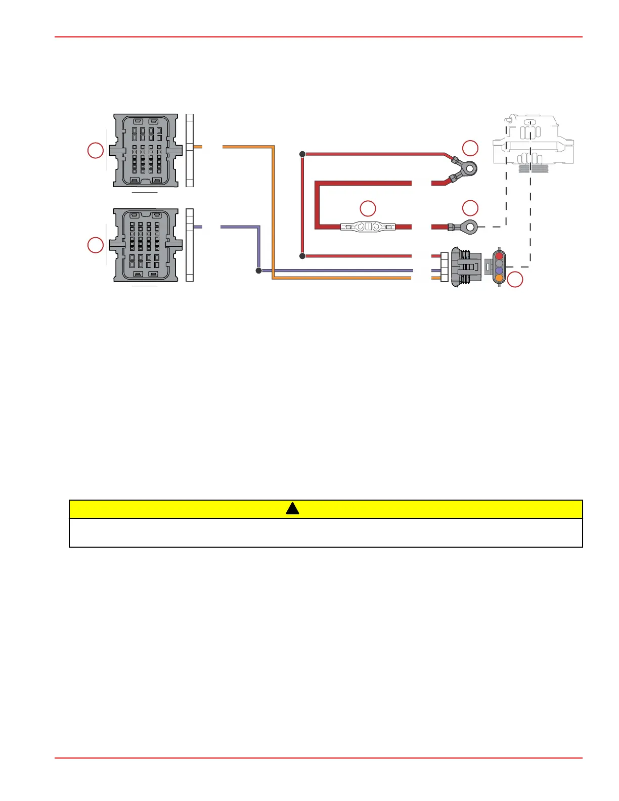
The charging system consists of the alternator, starting battery, 150‑amp fusible link, propulsion control module (PCM), and the
wiring that connects these components. The wiring diagram is shown, following.
a - PCM connector A (engine harness)
b - Hot stud (battery +)
c - PCM connector C (engine harness)
d - Fusible link (150 amp)
e - Alternator output
f - Alternator 4‑pin connector (engine harness)
Precautions
Observe the following precautions when working on the charging system. Failure to observe these precautions may result in
serious damage to the charging system.
• Do not attempt to polarize the alternator.
• Do not short across or ground any of the terminals on the alternator, except as specifically instructed.
• Never disconnect the alternator output lead, engine harness, or battery cables when the alternator is being driven by the
engine.
• Always remove the negative (–) battery cable from the battery before working on the charging system.
!
CAUTION
Disconnecting or connecting the battery cables in the incorrect order can cause injury from electrical shock or can damage
the electrical system. Always disconnect the negative (‑) battery cable first and connect it last.
• When installing the battery, be sure to connect the negative (–) battery cable to the negative (–) battery terminal and the
positive (+) battery cable to the positive (+) battery terminal. Connecting the battery cables to the battery in reverse will
melt the 150‑amp fusible link in the output lead of the alternator. The alternator will not be able to charge the battery, and
the battery will be quickly discharged if the engine is run.
• When using a charger or booster battery, connect it in parallel with the existing battery (positive to positive; negative to
negative).
Alternator Description
The alternator consists of a rotor, three‑phase stator, and rectifier bridge. As it is spun, the electromagnetic field in the rotor
induces an AC voltage in the stator, which is then converted to a DC voltage by the rectifier. The diodes in the rectifier also
prevent the battery from discharging back through the stator.
A voltage regulator controls the alternator's output to ensure that the battery is neither overcharged nor undercharged. The
regulator does this by sensing the voltage at the battery and limiting the rotor's field current accordingly. The alternator
self‑limits current: as long as the voltage is regulated within the prescribed limits, the alternator cannot produce excessive
current.
An excitation circuit supplies a small amount of current to the rotor field to initially start the electromagnetic field. Once the
alternator begins to produce output, field current is supplied solely by the rectifier diodes.
109B
109A
102B
PPL
ORN
RED
PPL
RED
ORN
RED
C1
A1
H4
A1
H4
G2
A
B
C
D
Charging and Starting System
90-8M0146617 eng JULY 2018 © 2018 Mercury Marine Page 6B-5
 Loading...


