Image Optimization 5-45
5.13.7.2 iPage Basic Functions and Operations
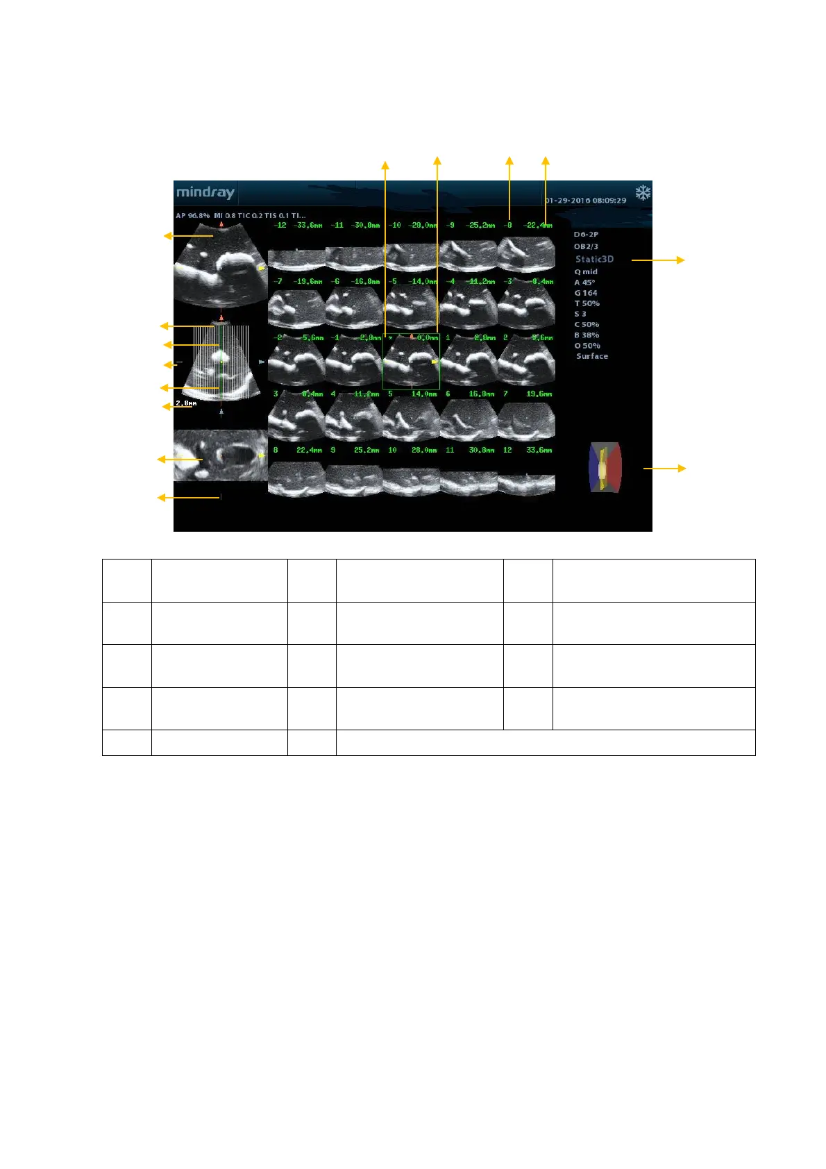
<1> A plane <2> B plane (the current
reference image)
<3> C plane
Central section line (Current
active section line)
<7> Section line <8>
Space between two
planes
<9> Image parameter
number
Section plane position (to the
central plane)
<13> Central plane mark <14> Green box on the active image
Layout
The system supports several types of display layout: 2*2, 3*3, 4*4 and 5*5. Click the
corresponding icon on the screen to select, and the selection [Slice Number] changes
accordingly.
Reference image
Click [A Plane], [B Plane] or [C Plane] to select the reference image.
Slice and slice line
Central slice: the central plane which corresponds to the central slice line is the
central slice, marked with a green “*” in the top-left corner of the image.
View vertical or horizontal slices.
Active slice: the central plane which corresponds to the green slice line is the active
slice, marked with a green box. The default active slice is the central slice.
Slice order number: indicates the order of the slices. The position of the central slice
is “0”, the slices before the central slice are marked with negative integral numbers,
and the slices after the central slice are marked with positive integral numbers.

 Loading...


