18
Mechanical Installation
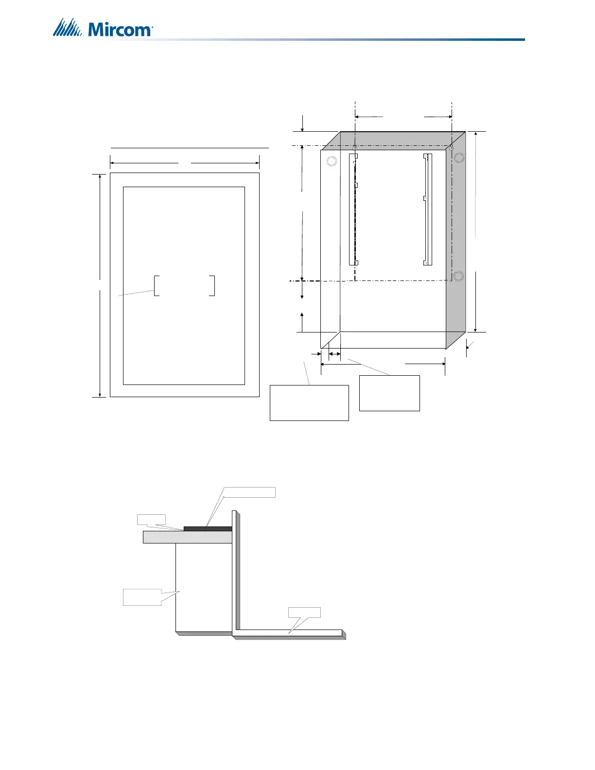
flush mount the backbox into the wall. Peel the adhesive cover from the trim ring and stick to
the wall surface around the backbox, after wall is finished.
Figure 3 Box dimensions, semi-flush mounting and trim ring
Figure 4 shows a cross-section of the semi-flush mounted enclosure and the trim ring. Make
sure to allow a minimum depth of 1” above the wall surface for proper door opening.
Figure 4 Flush trim detail (from above)
14.5"
4
.
5
"
11"
26"
1.5"
5.4"
20.5"
3.5"
1"
3.5" is the maximum
depth for semi-flush
mounting using the
flush trim ring
1" is the minimum depth
above the wall required for
semi-flush mounting using the
flush trim ring
17"
28.5"
Adhere trim ring to
wall surface around
FA-300 backbox.
PLACE FA-UNIV-TRB TRIM RING OVER BACKBOX
TRIM RING
WALL
WOOD OR
METAL STUD
BACKBOX
 Loading...


