22
Cable and Jumper Connections for Main Board and Adder Modules
6.1.1 Connectors and Jumpers on the Main Fire Alarm Board
6.2 ICAC-306 Input Class-A Converter Adder Module
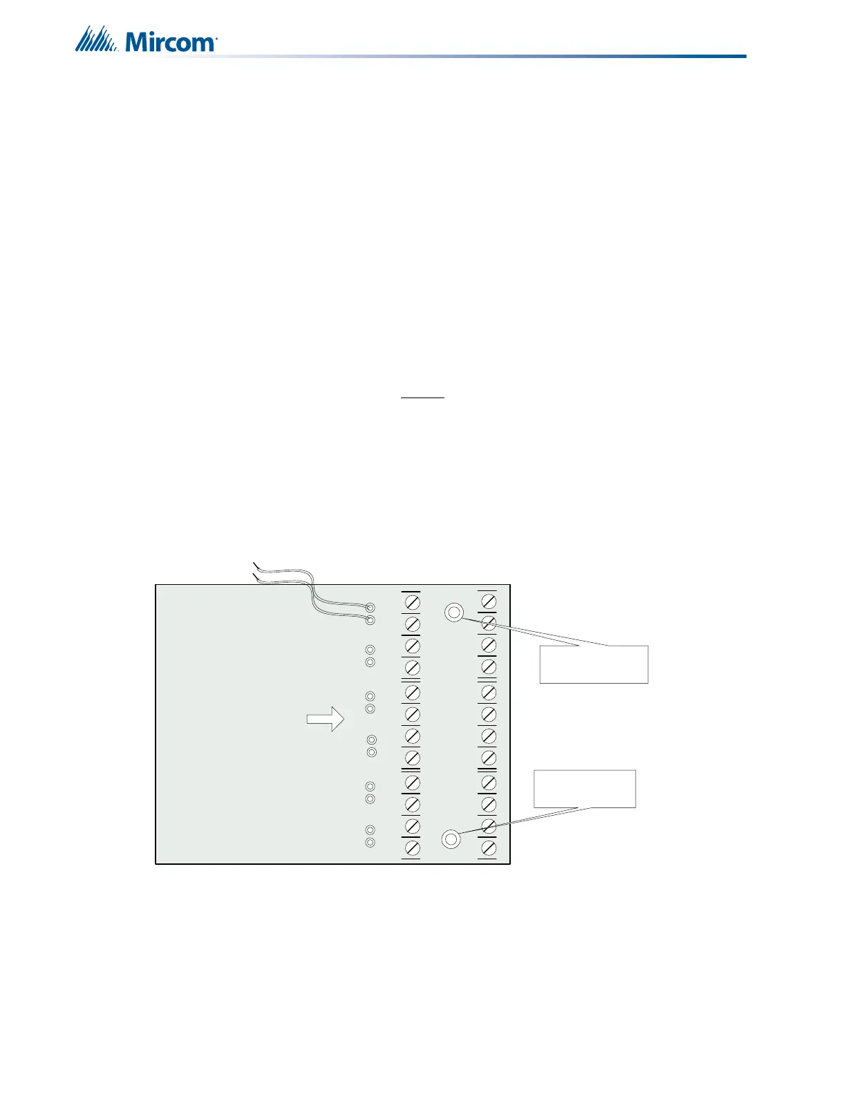
Figure 8 ICAC-306 Input Class-A Converter Adder Module
There are no jumpers or cables to set on this module, just wiring from the converter (wires are
fixed here) to the Main Fire Alarm Board.
Initiating circuits must be wired from the ICAC-306 module to the Main Fire Alarm board. For
example, Initiating circuit 1 positive (red) and negative (black) wires are connected to the
positive and negative terminals (respectively) of Initiating circuit 1 on the Main Fire Alarm
P5
Cable from P1 of the PR-300 Polarity Reversal and City Tie Module connects
here. Otherwise not used.
P6
Cable from connector P1 of the RM-312 or RM-306 Relay Adder Module
connects here. Otherwise not used.
JW1
On the Main Fire Alarm Module, this jumper must be removed if a PR-300
Polarity Reversal and City Tie Module is installed.
JW2 Remove this jumper if an RM-312 or RM-306 Relay Adder Module is used.
JW3 Removed all the time.
JW4
Normally open. Place jumper here and power down (AC and Batteries) then
power back to revert back to default password. Once the system has reset,
REMOVE the jumper from the pins at JW4. Leave normally open.
JW5
Normally open to BLOCK remote
configuration via modem, PC with a UIMA
converter module or a CFG-300 Configuration Tool. Place jumper here to ALLOW
any type of configuration.
JW6 Not used, open.
JW7 Not used, open.
BLK RED
BLK REDBLK REDBLK REDBLK REDBLK RED
- DET1 OUT+- DET2 OUT+- DET3 OUT+- DET4 OUT+- DET5 OUT+- D ET6 OU T+
- DET1 RET+- D ET2 R ET+- D ET3 R ET+- DET4 RET+- DET5 RET+- DET6 RET+
mounting hole for
#6-32 screws
All these pins comes with
red and black wires which
are connected to the
detection circuit on the
main fire alarm board. Red
is positive and black is
negative
ICAC-306
mounting hole for
#6-32 screws
 Loading...


