27
7.0 Field wiring
7.1 Main Fire Alarm Board Field Wiring
Wire devices to the terminals as shown in the figures that follow. Refer to the Wiring Tables for
wire gauges and to Appendix A for specifications.
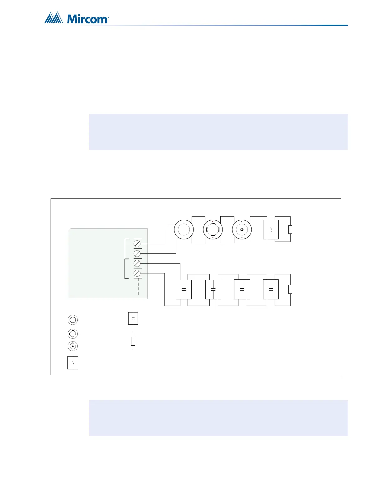
7.1.1 Initiating Circuit Wiring Class B
Wiring diagrams for the initiating circuits are shown below. The panel supports Class B (Style
B) and Class A (Style D) for the initiating circuits. The initiating circuits are supervised by a
3.9K End-of-Line Resistor or for power saving an Active-End-of-Line.
Figure 14 Initiating circuit – Class B or Style B wiring
Caution: Do not exceed power supply ratings.
Note: Depending on configuration, End-of-Line Resistors on initiating circuits must be
all 3.9K ohm resistors or all Active End-of-Line resistors.
+
-
STYLE B
WIRING
STYLE B
WIRING
INITIATING
CIRCUIT #1
INITIATING
CIRCUIT #2
INITIATING
CIRCUIT - 1
ALARM ZONE
INITIATING
CIRCUIT - 2
SUPERVISORY
ZONE
ION SMOKE
DETECTOR
PHOTO SMOKE
DETECTOR
HEAT
DETECTOR
PULL STATION
3.9K 1/2 WATT ELR
SUPERVISORY
FIRE ALARM MAIN BOARD
+
-
DET 1DET 2
NOTE: IF ACTIVE END OF LINE
RESISTORS ARE USED, THEY MUST
BE USED ON ALL INITIATING CIRCUITS.
 Loading...


