32
Field wiring
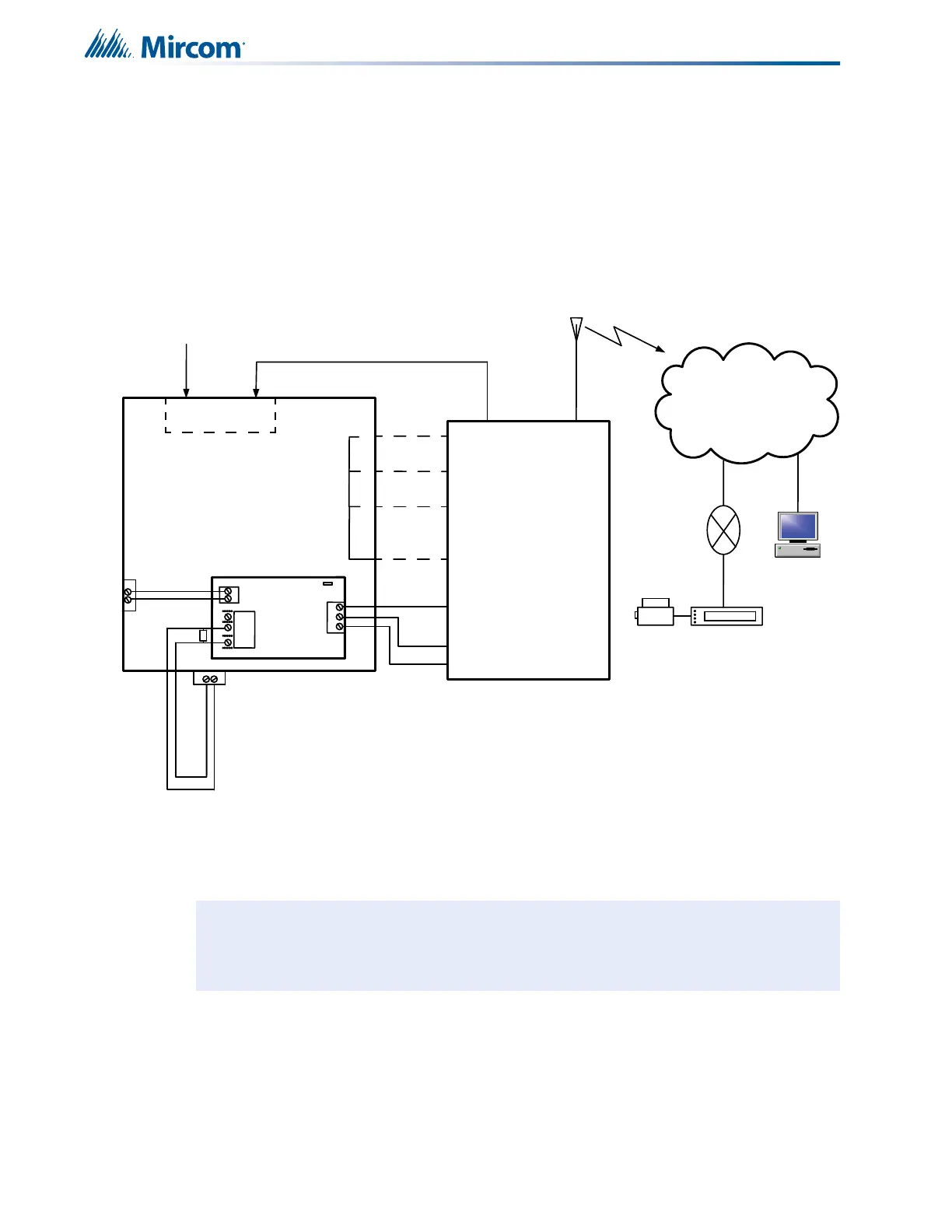
7.3 Connecting to a 3G4010 Interface Device for Canada
A typical connection is shown in Figure 22. The PCS-100 Passive Communications Interface
Board (sold separately) is required.
For information on Compatible DACR Receivers see 12.0 Appendix A: Compatible
Receivers on page 94.
Figure 22 Connecting an FA-300 FACP to a 3G4010 Interface Device
Note: The DSC interface device 3G4010 is required if the installation requires ULC
S559 certification. The DSC interface device 3G4010CF is required if the
installation requires UL864 9th edition certification.
A
L
A
R
M
R
E
L
A
Y
S
P
V
R
E
L
A
Y
T
R
B
L
R
E
L
A
Y
Telephone
Line A
Connection
DC IN
E
O
L
To GSM/GPRS
T
yp
ic
a
l
In
st
a
ll
a
tio
n
in
Ca
n
a
d
a
Line 2Line 1
PCS-100
P
O
W
E
R
2
4
V
G
N
D
P
G
M
4
G
N
D
1
4V
NC
C
O
M
N
O
T
B
L
R
E
L
AY
J
W
1
P
G
M
4
AUX SUPPLY
+
-
+
-
Internet
Computer
Printer
SUR-GARD
SYSTEM IV
Internal IP: X.X.X.X
External IP: X.X.X.X
SG-Systems
Console 2.1
Default Gateway: X.X.X.X
Sub-Net Mask:X.X.X.X
Port #: YYYY (UDP)
N
O
C
N
O
C
N
O
C
C
O
M
Z
3
Z
2
Z
1
T
1
R
1
(
-)
(
+
)
Conventional input
configured as 3G4010
radio trouble
FA-300
3G4010 TRBL
FA-300 - 3G4010 Connection - Typical Diagram
-
All units must be installed in the same room
-
All extended wiring must be in metallic conduit
-
Wiring between FACP and 3G4010: 18 m max.
Contact DSC to reprogram the zone inputs to match
the FACP as shown in this diagram
-
 Loading...


