30
Field wiring
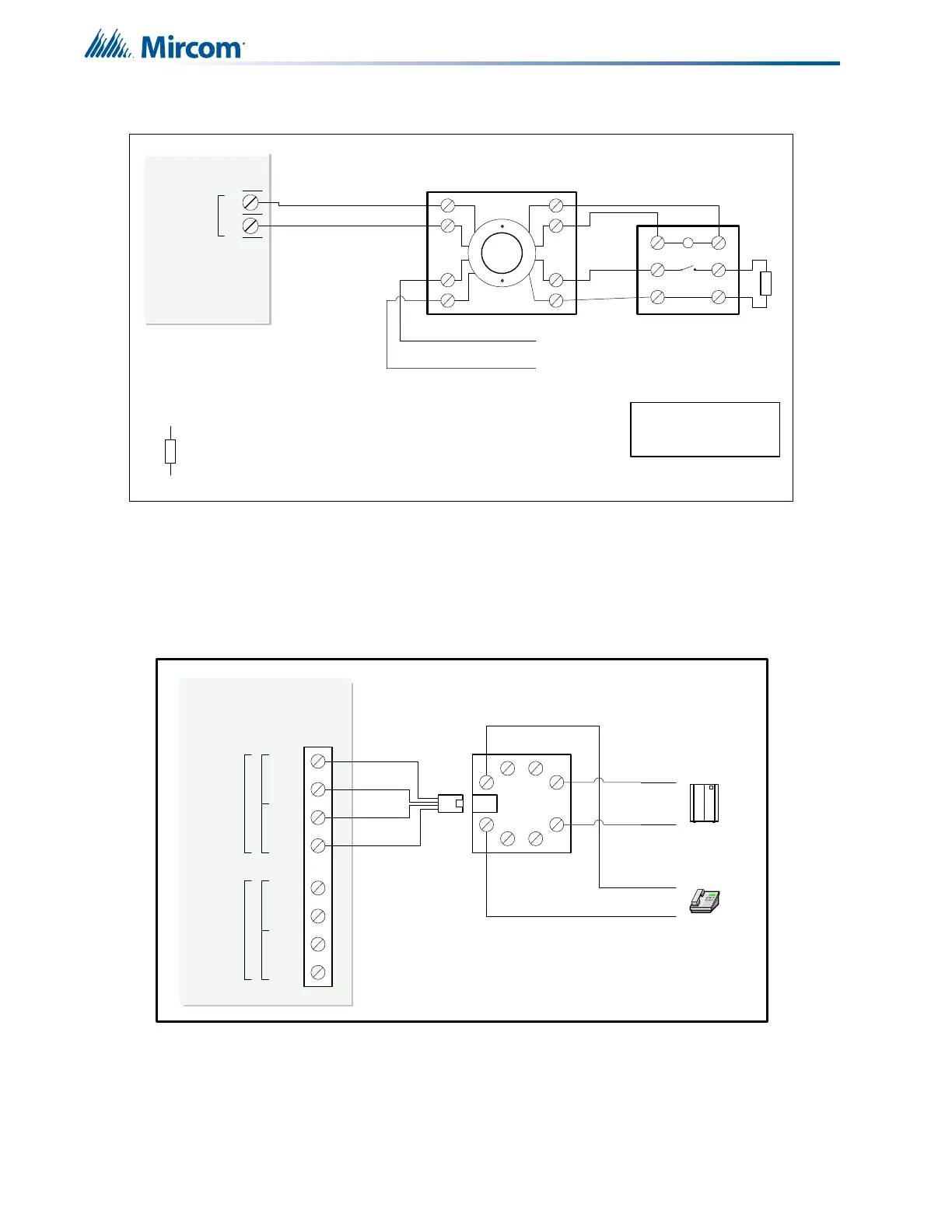
7.1.4 Four Wire Smoke Detector Wiring
Figure 18 Four-wire smoke detector wiring
7.1.5 Dialer Wiring
If you have Fire Alarm Panel Models FA-301-12LDW, FA-301-12LDR, and FA-301-8LDW
there is a dialer on board and terminals marked Line 1 and Line 2 must be wired as shown in
Figure 19 below.
Figure 19 Dialer wiring
POWER
DETECTION
++
++
--
--
1
4
2
3
5
6
TO INITIATING
CIRCUIT
RESETTABLE 4-WIRE SMOKE
DETECTOR POWER SUPPLY
22VDC, 200mA
MAX. CURRENT - 300mA
MAX. RIPPLE VOL. 5mV
(POWER LIMITED)
4-WIRE DETECTION DEVICE
END OF LINE RELAY
LISTED S3403
MODEL A77-716B
MANUFACTURED BY
SYSTEM SENSOR
+
-
4-WIRE
SUPPLY
3.9K 1/2 WATT ELR
LEGEND
NOTES
ALL POWER LIMITED CIRCUITS
MUST USE TYPE FPL, FPLR,
OR FPLP POWER LIMITED
CABLE
FIRE ALARM MAIN BOARD
TIPTIP RIN GRING
premise telephone
IF permitted
TIPTIP RIN GRING
LINE-1
LINE-2
1
23
4
8
5
76
Public switch
Telephone company
wiring
TIP
RING
TIP
RING
RJ31X
BROWN
GREY
GREEN
RED
COCO RESRES
Line 2 is Wired as shown for Line 1
FIRE ALARM MAIN BOARD
 Loading...


