60
Configuration with the CFG-300 LCD Service Tool
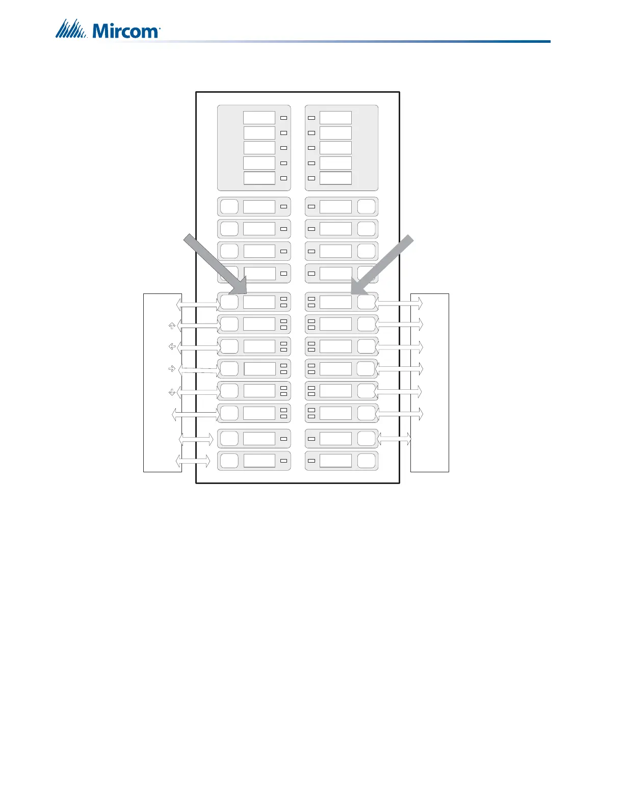
Figure 36 shows the function of the buttons on the front panel display.
Figure 36 FA-300 Configuration
11.1 Accessing Configuration Mode
To access configuration mode
1. Connect the CFG-300. See the document included with the CFG-300 for details.
2. On a single stage system, press the MENU button.
On a two stage system, press the LAMP TEST and ALM/SUP/TBL/BLDG AUDIBLE SIL
buttons simultaneously.
The CFG-300 displays the Main Menu.
3. Enter your passcode.
The minimum number of digits for the passcode is four and the maximum is ten. The
passcode must be numerical values only. The default passcode is 1111.
4. Press the ENTER button.
The main command menu appears.
WALK
TEST
REMOTE
TROUBLE
CP U FAULT
GRO UND
FAULT
SIGNAL
SILENCE
FIRE
DRILL
GENERAL
ALARM
SYSTEM
RESE T
AUX
DISCO NNEC T
LAMP
TEST (MENU)
ALM/SUP/TBL/
BLDG AUDIBLE
A.C.
ON
COMMON
ALARM
COMMON
SUPV
COMMON
TROUBLE
BATTERY
TROUBLE
ZONE-1
DISCO NNEC T
ZONE-3
DISCO NNEC T
ZONE-5
DISCO NNEC T
ZONE-7
DISCO NNE CT
ZONE-9
DISCO NNEC T
ZONE-11
DISCO NNEC T
ZONE-2
DISCO NNEC T
ZONE-4
DISCO NNEC T
ZONE-6
DISCO NNEC T
ZONE-8
DISCO NNEC T
ZONE-10
DISCO NNEC T
ZONE-12
DISCO NNEC T
NAC-1
DISCO NNEC T
NAC-3
DISCO NNECT
NAC-2
DISCO NNEC T
NAC-4
DISCO NNEC T
0
2
4
6
8
*
1
3
5
7
9
#
ENTER
INFO
CANCEL
10 Q Z
2 A B C 3 D E F
4 G H I
5 J K L
6 M N O 7 P R S
8 T U V 9 W X Y
BACK SPACE Forward
SIL (MENU)
Use these
buttons for
configuration.
Their functions
are printed under
the label.
Use these
buttons for
configuration.
Their functions
are printed
under the label.
AUTOMATIC
ALARM SIGNAL
CANCEL
 Loading...


