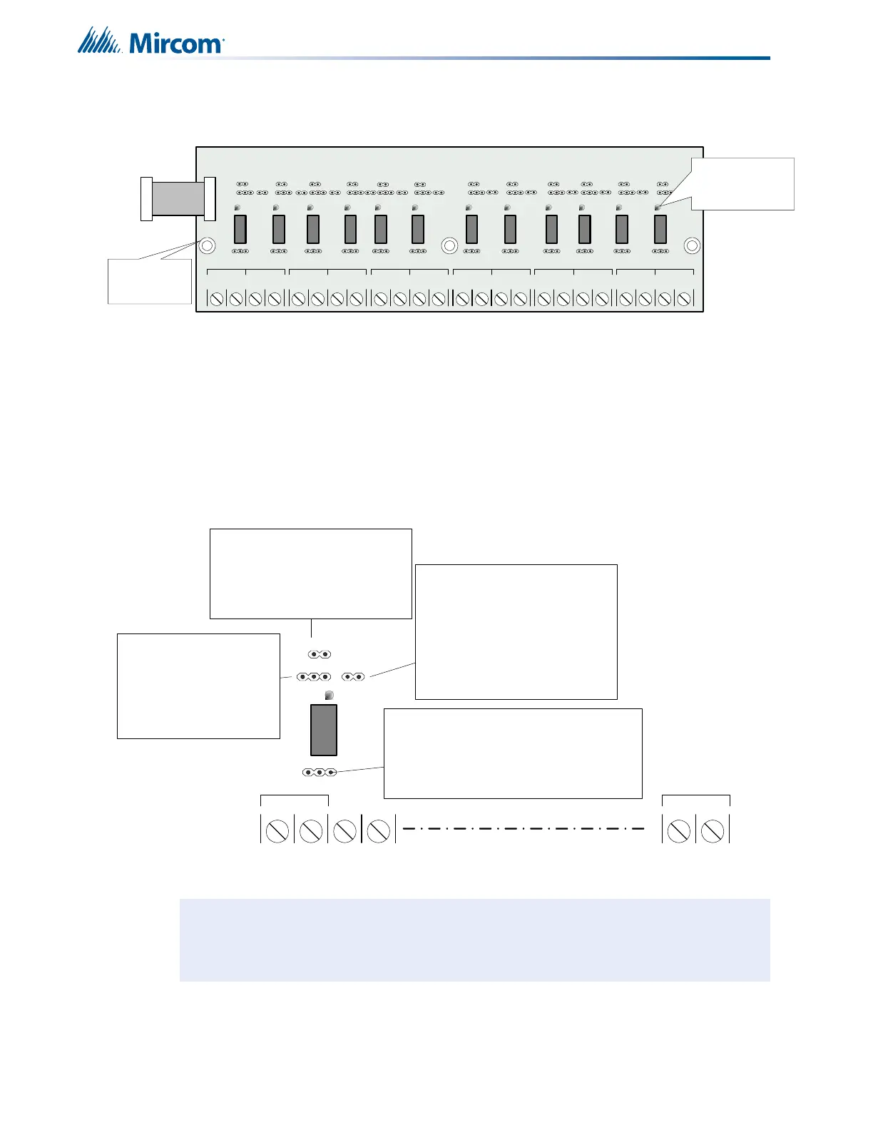
EasyManuals Logo
Home>Mircom>Control Panel>FA-301-12LDR

Mircom FA-301-12LDR User Manual

Mircom FA-301-12LDR
106 pages
To Next Page IconTo Next Page
To Previous Page IconTo Previous Page
Page #24 background imageLoading...
Page #24 background image
24
Cable and Jumper Connections for Main Board and Adder Modules
jumpers located below the relays are used to select either normally open contacts or normally
closed contacts.
Figure 10 RM-312 twelve relay adder module
6.4.2 Programming the relays
A typical relay circuit is shown in Figure 11 with the jumper locations and descriptions.
Figure 11 RM-312/306 Relay programming
P1 Cable from RM-312 Relay Adder Module connects to P6 on Main Fire Alarm
Board.
Note: Relay programming should be done before installing the board.
NO/NC C
RELAY 1
NO/NC C
RELAY 2
NO/NC C
RELAY 3
NO/NC C
RELAY 4
C
RELAY 5
NO/NC C
RELAY 6
NO/NC C
RELAY 7
NO/NC C
RELAY 8
C
RELAY 9
NO/NC C
RELAY 10
NO/NC C
RELAY 11
NO/NC C
RELAY 12
NO/NC NO/NC
Three mounting
holes for #6-32
screws
INDIVIDUAL
GREEN RELAY
STATUS LEDs
Connect to P6 on the
main fire alarm board
NO NC
SA
Z1
1&2
NO/NC C
RELAY 1
NC/NO CONNECTION
NC: terminal provides normally closed contacts
NO: terminal provides normally open contacts
Default: jumper is installed on normally open (NO)
Note: if the jumper is not installed on any selection
then the relay is not connected to the terminals
SUPV/ALARM SELECTION
S: Relay turns ON when common
supervisory is active
A: Relay turns ON when common
alarm is active
Default: No jumper installed,
connected on center pin only
ZONE JUMPER
installed: turns ON relay when the zone
(1) is active
removed: does not turn ON the relay when
zone (1) is active
Default: Jumper is installed
LOGICAL OR WITH ADJACENT ZONE
jumper installed: this relay 1 works in
conjunction with relay 2
jumper removed: relay 1 does not
operate with the adjacent relay 2
chaining example:if jumper is installed
on 1&2 and 2&3 then all the three relays
will be ON if any one of relays 1,2 and 3 is
active
Default: No jumper installed, connected
on one pin only
NO/NC C
RELAY 12
RELAY
LED (GREEN)
i

Table of Contents

Other manuals for Mircom FA-301-12LDR

Questions and Answers:

Question and Answer IconNeed help?

Do you have a question about the Mircom FA-301-12LDR and is the answer not in the manual?

Mircom FA-301-12LDR Specifications

General IconGeneral
BrandMircom
ModelFA-301-12LDR
CategoryControl Panel
LanguageEnglish

Related product manuals