20
Mechanical Installation
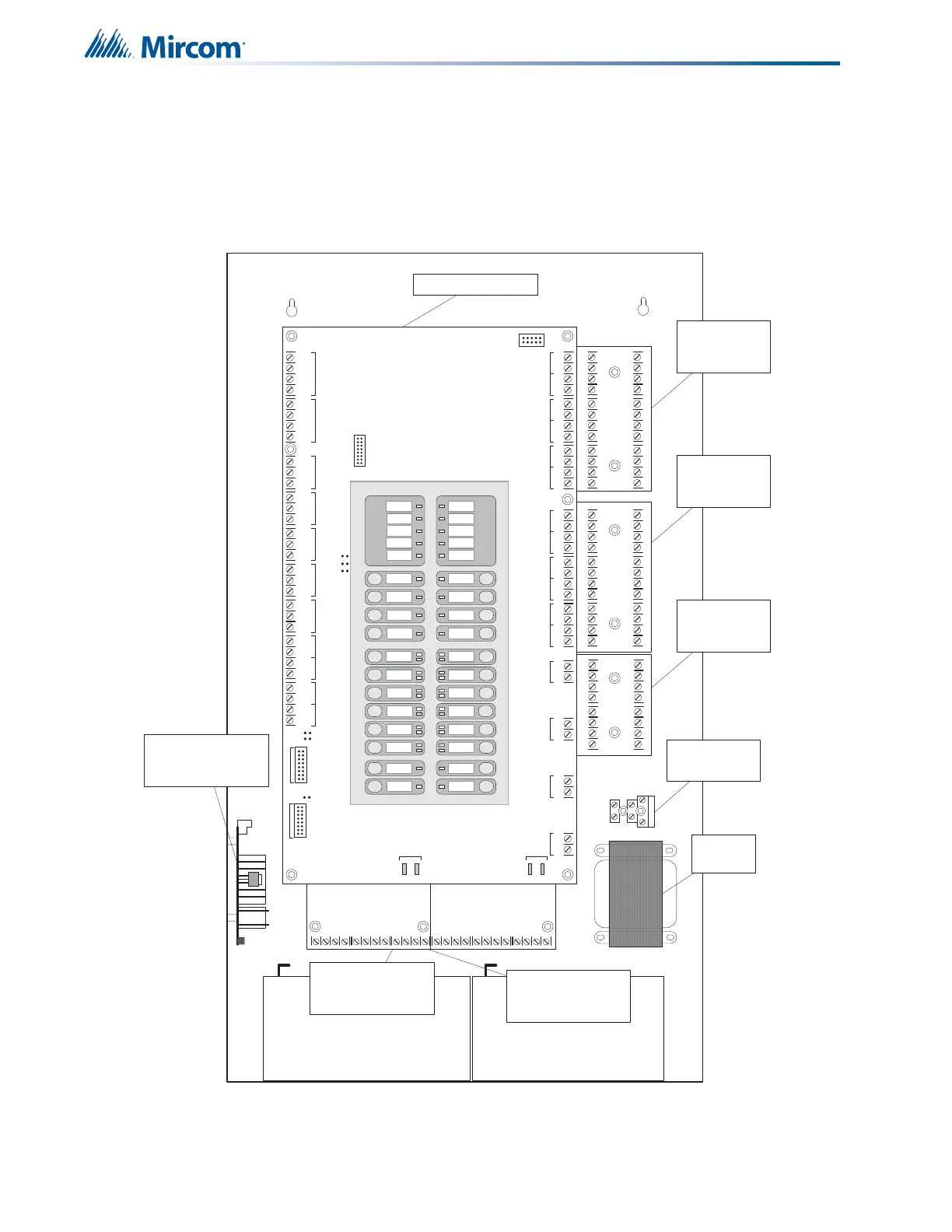
5.3 Installing the Adder Modules
FA-300 Series Fire Alarm panels come pre-assembled with all components and boards except
for Adder Modules. Module installation locations are shown in Figure 6. Refer to Figure 7 on
the next page for jumper and DIP switch settings and see 7.7 Wiring Tables and
Information on page 36 for wiring specifications.
Figure 6 Installation of Adder Modules
Fuse and AC
wiring terminal
S-+NC NOCNC NOCNC NOCNC NOC
+-+-COM(+)
COM(-)
TRLTRB RTRT
RTR T
RES CO RES C O
LINE1LINE 2
WALK
TEST
REMOTE
TROUBLE
CPU FAULT
GROUND
FAULT
SIGNAL
SILENCE
FIRE
DRILL
AUTOMATIC
ALARM SIGNAL
CANCEL
GENERAL
ALARM
SYSTEM
RESET
AUX
DISCONNECT
LAMP
TEST
ALM/SUP/TBL/BLDG
AUDIBLE SIL
A.C.
ON
COMMON
ALARM
COMMON
SUPV
COMMON
TROUBLE
BATTERY
TROUBLE
ZONE-1
DISCONNECT
ZONE-3
DISCONNECT
ZONE-5
DISCONNECT
ZONE-7
DISCONNECT
ZONE-9
DISCONNECT
ZONE-11
DISCONNECT
ZONE-2
DISCONNECT
ZONE-4
DISCONNECT
ZONE-6
DISCONNECT
ZONE-8
DISCONNECT
ZONE-10
DISCONNECT
ZONE-12
DISCONNECT
NAC-1
DISCONNECT
NAC-3
DISCONNECT
NAC-2
DISCONNECT
NAC-4
DISCONNECT
JW3
JW2
JW1
-+-+-+-+-+-+-+-+-+-+-+-+-+-+-+-+
DET 1DET 2DET 3DET 4DE T 5DET 6DE T 7DET 8DET 9DE T 1 0DET 11DET 12SI G 1SIG 2SIG 3SIG 4
JW 6
JW 5
JW 4
TO PR -300 MOD ULE
TO RM-312/RM-306 RELAY
MODULE
RS-
485
AUX. RELAYALA RM
REL AY
SU PE RVIS O RY
RELAY
TR OU BLE
RELA Y
AU X
SUPPLY
4- W I RE
SUPPLY
UNFILTERED
RTI
PORT
P
1
P
2
P
3
P
4
+
_
BATTERY SEC. TX
BATTERY BATTERY
CLASS-A converter
board for detection
circuits ICAC-306 (6
cir cuits )
CLASS-A converter
board for detection
circuits ICAC-306 (6
cir cuits )
CLASS-A converter
board for indicating
circuits OCAC-304
(4 circuits)
Reverse polarity and city
tie module PR-300.
Mounted on hex spacer
with two screws provided
Relay Module RM-306
Mount relay module on the
left side using two screws
provided .
Relay Module RM-312
centre under main fire
alarm board using three
screws provided .
Transformer
Fuse and AC wirung
terminal
MAIN FIRE PANEL BOARD
Fuse and AC
wiring terminal
 Loading...


