36
Field wiring
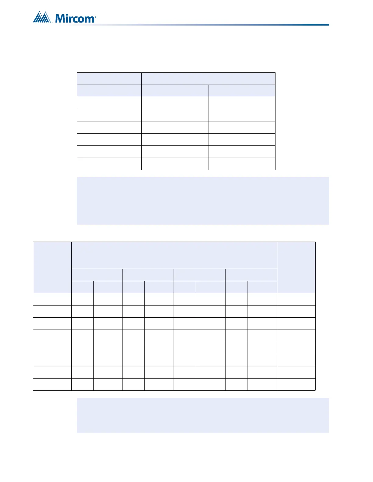
7.7 Wiring Tables and Information
Table 3 Initiating Circuit Wiring
Wire gauge Maximum wiring run to last device
AWG Feet Meters
22 2990 910
20 4760 1450
18 7560 2300
16 12000 3600
14 19000 5800
12 30400 9200
Notes: For Class A the maximum wiring run to the last device is divided by two.
Maximum loop resistance should not exceed 100 ohms.
Maximum capacitance of 0.5 μF total on each initiating circuit.
Table 4 Indicating Circuit Wiring
Total
signal
load in
Amperes
Maximum wiring run to last device
Max. loop
resistance
in ohms
18 AWG 16 AWG 14 AWG 12 AWG
Feet Meters Feet Meters Feet Meters Feet Meters
0.06 2350 716 3750 1143 6000 1829 8500 2591 30
0.12 1180 360 1850 567 3000 915 4250 1296 15
0.30 470 143 750 229 1200 366 1900 579 6
0.60 235 71 375 114 600 183 850 259 3
0.90 156 47 250 76 400 122 570 174 2
1.20 118 36 185 56 300 91 425 129 1.5
1.50 94 29 150 46 240 73 343 105 1.2
1.70 78 24 125 38 200 61 285 87 1.0
Notes: For Class A wiring the resistance in ohms is multiplied by two.
Maximum voltage drop should not exceed 1.8 volts.
 Loading...


