39
Turning on the Panel
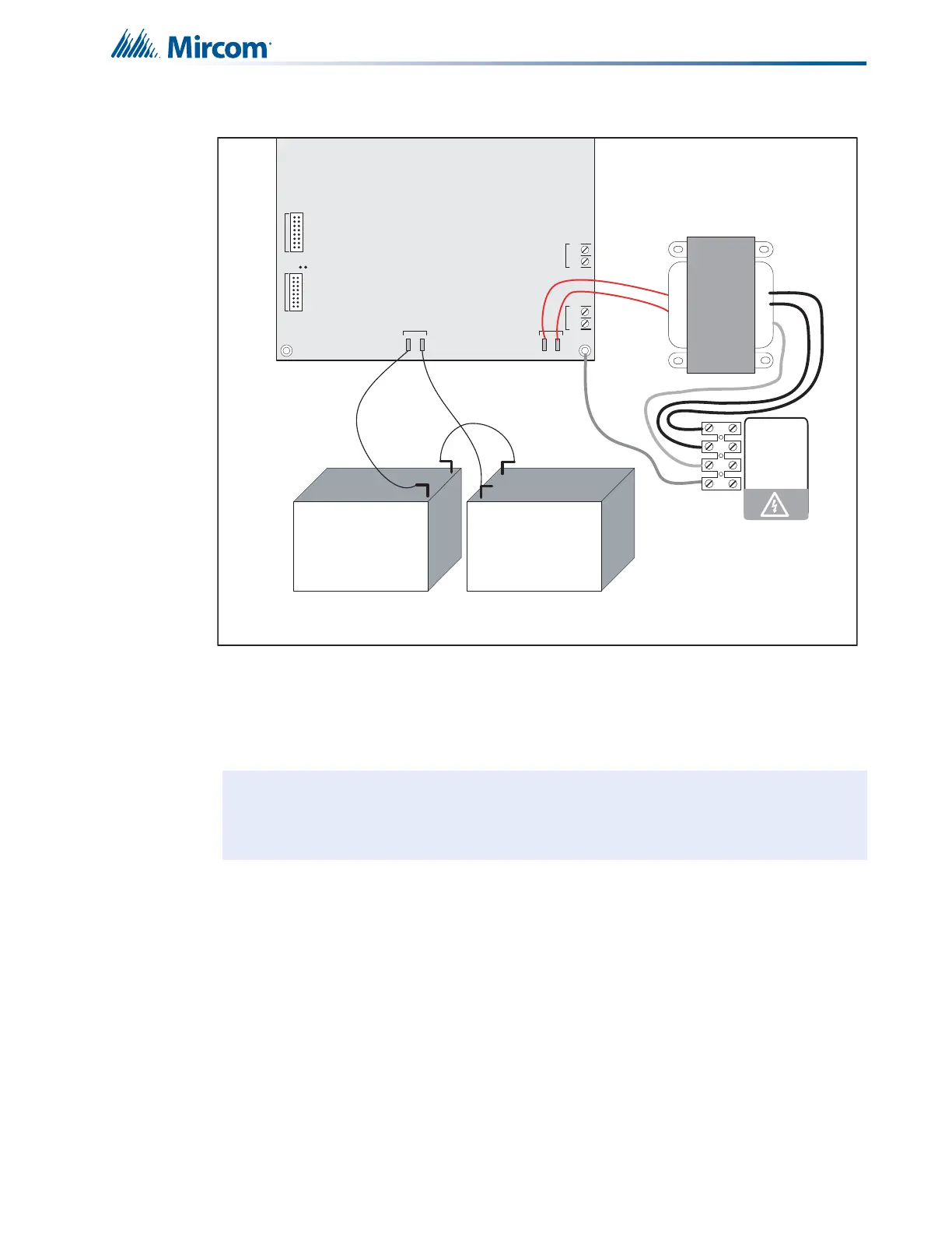
Figure 26 Battery connections
All indicators should be off except for the green A.C. ON LED and the green Trouble Relay
LED on the left side of the main board. It is shown in Figure 7 on page 21
.
4. Configure the Fire Alarm Control Panel as described in 11.0 Configuration with the CFG-
300 LCD Service Tool on page 59.
Note: The green Trouble Relay LED on the left side of the main board is illuminated
when the system is normal. This LED is for diagnostics and indicates that the
Trouble Relay is in normal standby condition.
JW1
-+-+
SIG 3SIG 4
TO PR- 30 0 MO DULE
TO RM-312/RM-306 RELAY
MOD U LE
P1 P2
P3 P4
+
_
BATTERY
SEC. TX
blk
red
red
red
red
blk
+
+
_
_
Battery Battery
NOTE: TO PREVENT SPARKING, CONNECT BATTERIES AFTER THE
SYSTEM MAIN A.C. POWER IS TURNED ON
red
green
blk
yellow
240 VAC 50Hz
120 VAC 60Hz
N
GND
 Loading...


