3Installing the option devices
Installing the forearm external wiring set/base external wiring set
3-89
3.6.2 Installing the base external wiring set
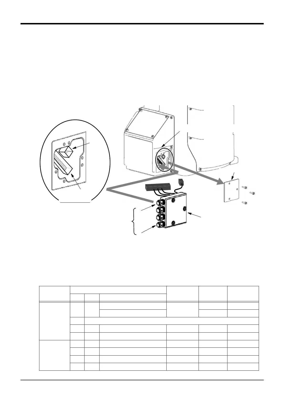
The installation summary of the base external wiring set is shown bellow. Mounts this option instead of the
CONBOX cover R.
Note) Although the robot's figure described to each page is RV-4FR series, the method is the same on other
robot series.
1) Loosen the fixing screws (three M4x16 screws) of CONBOX cover R and remove the box.
2) The connector: LAN, CNOP1 is in CONBOX cover R. The connector is previously attached to the connector
CNOP1. Removes this connector.
3) Connects the connector of base external wiring set to the connector of robot arm side. Connect with the
same name.
Fig.3-9 : Installing the base external wiring set (1F-HA01S-01, 1F-HA02S-01)
4) Install base external wiring set on the position where CONBOX cover R was being installed, by using original
three fixing screws. Installs carefully so that the cable etc may not be inserted.
5) Connects the cable of base external wiring set to the multifunctional electric hand, force sensor interface etc
which customer will use. The outlet and cable names of each cables are shown in Table 3-20.
Table 3-20 : Cable to pull out and outlet
Base external
wiring set
Cable to pull out Robot side
connection
connector
Grounding
process
Installation of
ferrite core
Outlet Name Purpose of use
1F-HA01S-01
<1> E ・ F1
Multifunctional electric hand CNOP1 Not require Require
Force sensor interface Require Not require
<2>
Reserved
<3> LAN
Vision sensor controller
LAN Not require Not require
<4> RIO
Multifunctional electric hand controller
CNOP1 Not require Require
1F-HA02S-01
<1> E ・ F2
Force sensor interface CNOP1 Require Not require
<2> E ・ F1
Multifunctional electric hand controller
CNOP1 Not require Require
<3> LAN
Vision sensor controller
LAN
Not require Not require
<4> RIO
Multifunctional electric hand controller
CNOP1 Not require Require
CONBOX cover R
Connecting connector (two connectors)
(Inside the CONBOX cover R)
<1>
<2>
<3>
<4>
~
Customer wiring side
Cable outlet
(Refer to Table 3-20.)
Base external wiring set
LAN
CNOP1
Connectors details
CNOP1
LAN
 Loading...


