2Unpacking to Installation
Installation
2-17
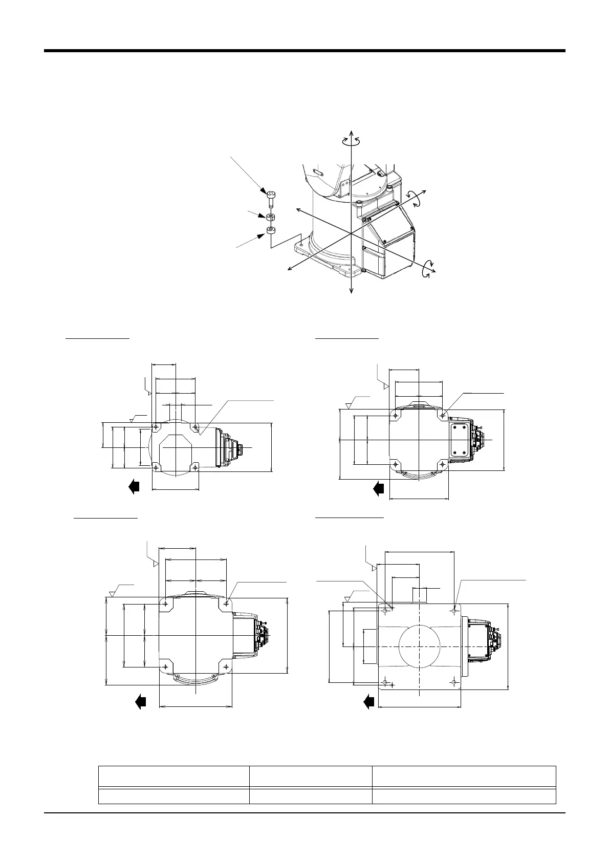
2.2.4 Installation procedures
The installation procedure of the robot arm is shown below.
Fig.2-7 : Installation dimensions
1) The robot installation surface has been machine finished. Use the installation holes opened at the four cor
-
ners of the base, and securely fix the robot with the enclosed installation bolts.
Model Installation hole size Installation bolt (attachment)
RV-2FR/4FR/7FR series 4-φ9 M8 hexagon socket head cap screw
㻔㻞㻜㻜㻕
㻝㻜㻞
㻤㻜 㻤㻜
㻝㻜㻞
㻔㻝㻢㻜㻕
㻔㻝㻢㻜㻕
㻔㻞㻜㻜㻕
㻠㻙䃥㻥
㼕㼚㼟㼠㼍㼘㼘㼍㼠㼕㼛㼚㻌㼔㼛㼘㼑
㻤㻜㻤㻜
㻝㻞㻤
㻔㻵㼚㼟㼠㼍㼘㼘㼍㼠㼕㼛㼚㻕
㻔㻵㼚㼟㼠㼍㼘㼘㼍㼠㼕㼛㼚㻕
㻾㼦㻞㻡
㻾㼦㻞㻡
㻔㻝㻢㻜㻕
㻔㻵㼚㼟㼠㼍㼘㼘㼍㼠㼕㼛㼚㻕
㻔㻵㼚㼟㼠㼍㼘㼘㼍㼠㼕㼛㼚㻕
㻾㼦㻞㻡
㻾㼦㻞㻡
㻤㻞
㻢㻣㻚㻡 㻢㻣㻚㻡
㻤㻞
㻔㻠㻜㻕
㻔㻝㻞㻜㻕
㻔㻝㻟㻡㻕
㻢㻣㻚㻡㻢㻣㻚㻡
㻔㻝㻟㻡㻕
㻔㻝㻢㻜㻕
㻠㻙䃥㻥
㼕㼚㼟㼠㼍㼘㼘㼍㼠㼕㼛㼚㻌㼔㼛㼘㼑
㻔㻵㼚㼟㼠㼍㼘㼘㼍㼠㼕㼛㼚㻕
㻔㻵㼚㼟㼠㼍㼘㼘㼍㼠㼕㼛㼚㻕
㻝㻜㻞㻚㻡㻝㻜㻞㻚㻡
㻔㻞㻜㻡㻕
㻝㻞㻠㻚㻡
㻝㻞㻠㻚㻡
㻝㻜㻞㻚㻡 㻝㻜㻞㻚㻡
㻠㻙䃥㻥
㼕㼚㼟㼠㼍㼘㼘㼍㼠㼕㼛㼚㻌㼔㼛㼘㼑
㻔㻞㻜㻡㻕
㻞㻠㻡
㻝㻢㻞
㻞㻠㻡㻚㻣
㻾㼦㻞㻡
㻾㼦㻞㻡
㻾㼛㼎㼛㼠
䇻
㼟㻌㼒㼞㼛㼚㼠
㻾㼛㼎㼛㼠
䇻
㼟㻌㼒㼞㼛㼚㼠 㻾㼛㼎㼛㼠
䇻
㼟㻌㼒㼞㼛㼚㼠
㻾㼛㼎㼛㼠
䇻
㼟㻌㼒㼞㼛㼚㼠
㻾㼦㻞㻡
㻾㼦㻞㻡
㻞㻙䃥㻤㻴㻣㻌㼞㼑㼍㼙㼑㼞
㻠㻙䃥㻝㻠
㼕㼚㼟㼠㼍㼘㼘㼍㼠㼕㼛㼚㻌㼔㼛㼘㼑
㻔㻵㼚㼟㼠㼍㼘㼘㼍㼠㼕㼛㼚㻕
㻔㻵㼚㼟㼠㼍㼘㼘㼍㼠㼕㼛㼚㻕
㻟㻜㻜
㻞㻡㻜
㻝㻟㻡
㻝㻡㻡
㻝㻡㻡
㻝㻟㻡
㻝㻞㻜
㻟㻜㻜
㻞㻡㻜
㻝㻜㻜
㻡㻜
䠢
䠤
䠢
䠤
䠩
䠨
䠢
䠤
䠢
䠤
䠩
䠨
䠢
䠲
䠢
䠲
䠩
䠰
RV-7FR series
<Bottom view>
RV-13FR
series
Spring washer
Installation bolt
RV-2FR series: 4-M8×35
RV-4FR/7FR series: 4-M8×40
RV-13FR series: 4-M12×55
RV-4FR series
Plain washer
RV-2FR series
 Loading...


