3Installing the option devices
Installing the operating range change (RV-2FR series)
3-49
(3) Installation procedure
The installation procedure of the J1 axis operating range change is shown below.
When installing this option, you should move the J1 axis to the 0 degrees by jog operation previously, and do this
work.
When installing this option for safety, you should cut off the power supply of the con
-
troller.
Each screw should be tightened with 9.5 Nm torque. Please confirm the screws are
surely tightened by 9.5 Nm torque before moving the robot.
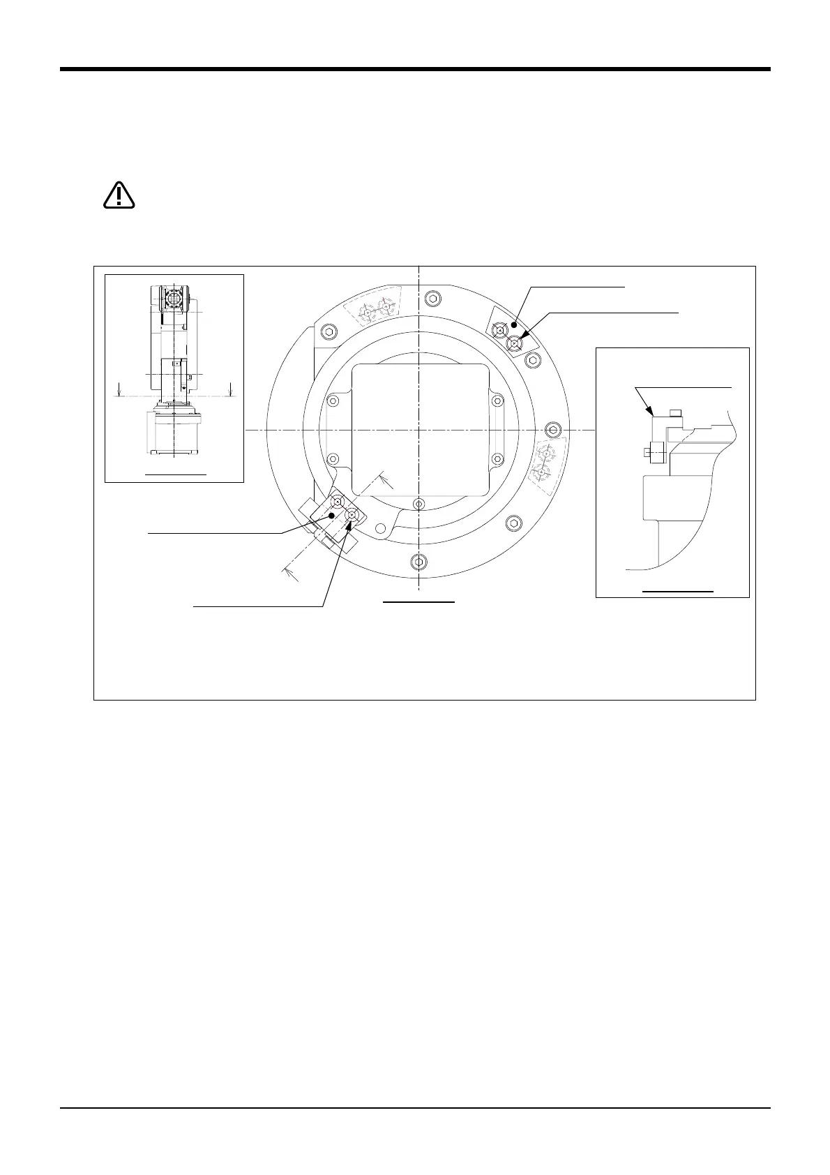
Fig.3-1 : Installation procedure of optional stoppers
1) Refer to Table 3-8 and confirm the installation position of the fixing stopper corresponding to the angle to
change.
With the combination of angles of a plus side and a minus side, the fixing stoppers are required to install on
two places.
2) Refer to Fig. 3-1 and install the fixing stopper to the installation position corresponding to the angle to
change. Tighten the screw firmly to fix the fixing stopper. (Tightening torque: 9.5 Nm)
3) Install the variable stopper block to the position shown in Fig. 3-1. Tighten screws firmly to fix the variable
stopper block as well as the fixing stopper. (Tightening torque: 9.5 Nm)
(4) Setting the parameter
Specify the operating range to parameter MEJAR and the mechanical stopper angle to parameter MORG with
appropriate values (variable angles given in Table 3-8) by the following steps.
1) Turn on the power supply.
2) Set up the operating range changed into parameter MEJAR.
MEJAR: (J1 minus (-) side, J1 plus (+) side, ***, ***, ***, ***, ...).
3) Set up the + side mechanical stopper angle changed into parameter MORG.
MORG: (J1 plus (+) side mechanical stopper angle, ***, ***, ...).
Note) Refer to the separate "Instruction manual/Detailed Explanation of Functions and Operations" for the
details of the setting method.
Section Z-Z
A
B
C
Variable stopper block
Variable
stopper block
Fixing stopper
Screw (2-M5x20 )
* Characters A, B, and C in this illustration correspond to the same characters in Table 3-8.
This illustration is an example of installing the fixing stopper at position B. When the fixing stopper is attached to the
position of A or C, the stopper will be attached as the dashed line showed.
The variable stopper block is always attached to the position shown in this illustration irrespective of a changed
angle of the J1 axis operating range.
Screw (2-M5x20)
Section Y-Y
 Loading...


