4-104
Maintenance and inspection procedures
5Maintenance and Inspection
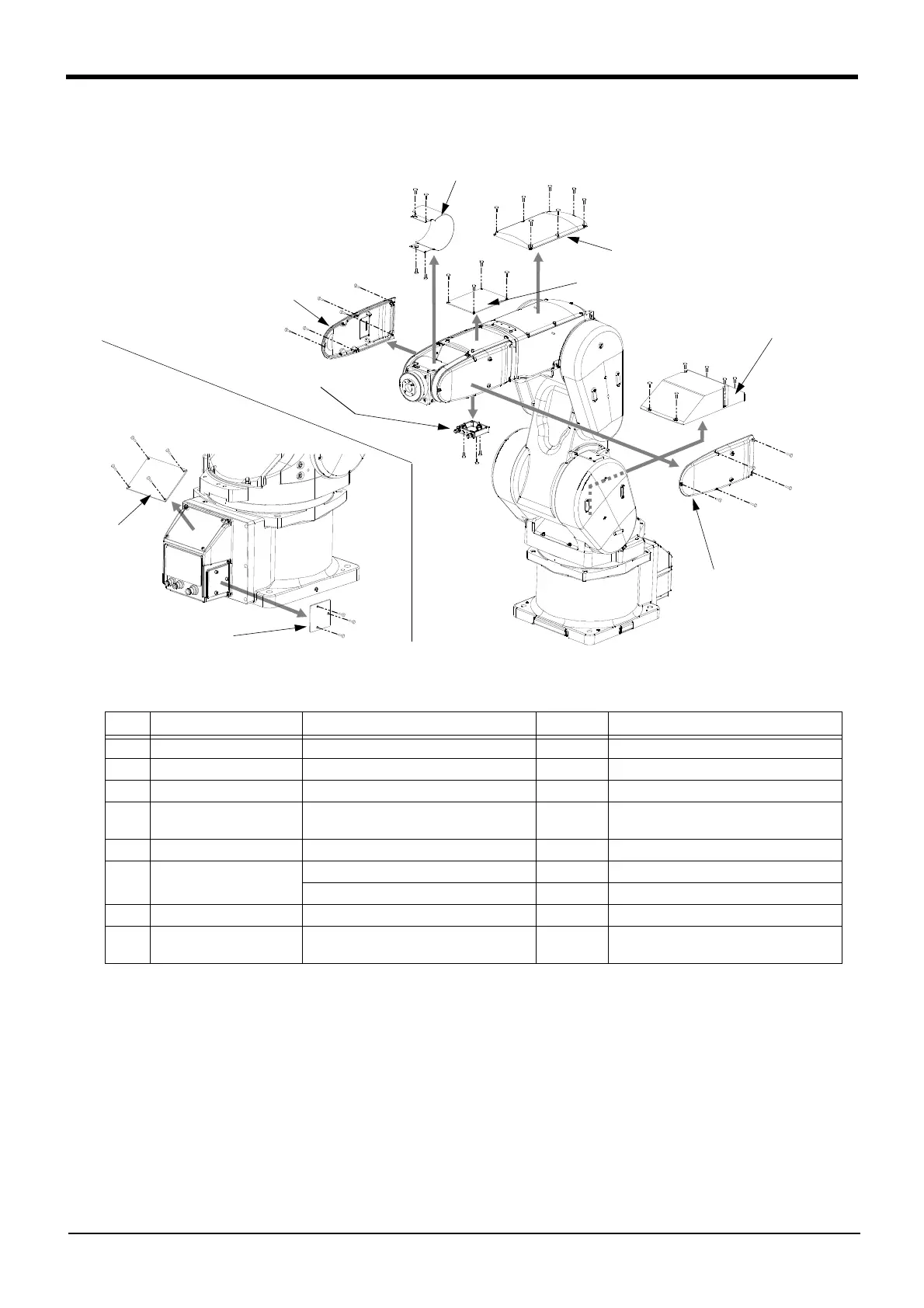
(3) RV-13FR series
Fig.5-6 : Installing/removing the cover (RV-13FR series)
Table 5-6 : Cover names and installation screw list (RV-13FR series)
(1) Refer to Fig. 5-6, and remove the covers.
(2) The names of the cover and installation screw are given in Table 5-6. The number in Table 5-6 correspond
to Fig. 5-6.
(3) Depending on the robot's posture, some covers are hard to be removed. In such a case, change the robot's
posture by performing jog operation to remove the covers.
(4) When removing the wrist cover, move the J5 axis to the position of +90 degrees by jog operation.
(5) When reattaching the covers after a maintenance inspection, proceed in the reverse order of their removal.
Tightening the screw with the torque shown in Table 5-6.
No.
Cover names
Installation screws
Note1)
Note1) The tightening torque of each screws are shown below.
M3 screw: 0.608 - 0.824 N·m
M4 screw: 1.39 - 1.89 N·m
Qty
Remarks
<1> No.2 arm cover U Hexagon socket head cap screw, M4 x 12 4
<2> No.2 arm cover Hexagon socket head cap screw, M4 x 12 5/one side Fix five screws on one side.
<3> Elbow cover Hexagon socket head cap screw, M4 x 12 7
<4> Cable clamp box Hexagon socket head cap screw, M4 x 16 3 Only protection specification has seal
washer M4
<5> Shoulder cover Hexagon socket head cap screw, M4 x 12 6
<6> Wrist cover Low head cap screw, M3 x 8 4 For RV-7FRLL
Hexagon socket head cap screw, M3 x 8 4 For RV-13FR/13FRL/20FR
<7> CONBOX cover Hexagon socket head cap screw, M4 x 8 4
<8> CONBOX cover R Hexagon socket head cap screw, M4 x 20 4 Only protection specification has seal
washer M4
RV-13FR series
<1> No.2 arm cover U
<2> No.2 arm cover
<2> No.2 arm cover
<3> Elbow cover
<4> Cable clamp box
<6> Wrist cover
<5> Shoulder cover
<7> CONBOX
cover
<8> CONBOX cover R
 Loading...


